1.3. Process (thermal) design procedure
Shell and tube heat exchanger is designed by trial and error calculations. The main steps of design following the Kern method are summarized as follows:
Step #1. Obtain the required thermophysical properties of hot and cold fluids at the caloric temperature or arithmetic mean temperature . Calculate these properties at the caloric temperature if the variation of viscosity with temperature is large. The detailed calculation procedure of caloric temperature available is in reference [3] (page 93-99) .
Step #2. Perform energy balance and find out the heat duty (Q) of the exchanger.
Step #3. Assume a reasonable value of overall heat transfer coefficient (U o,assm ). The value of (U o,assm ) with respect to the process hot and cold fluids can be taken from the books ([3] page 840 Table 8; [4] page 297 Table 8.2.)
Step #4 . Decide tentative number of shell and tube passes (np). Determine the LMTD and the correction factor FT ([3] page 828-833 Figs. 18-23; [4] page 292 Figs. 8.10a & 8.10b). FT normally should be greater than 0.75 for the steady operation of the exchangers. Otherwise it is required to increase the number of passes to obtain higher FT values.
Step #5 . Calculate heat transfer area ( A ) required: ![]() (1.1)
(1.1)
Step #6 . Select tube material, decide the tube diameter (ID= di, OD =do ), its wall thickness (in terms of BWG or SWG) and tube length (L). Calculate the number of tubes (nt) required to
provide the heat transfer area
( A ) calculated: ![]() . (1.2)
. (1.2)
Calculate tube side fluid velocity, 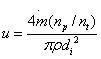 . (1.3)
If u <1 m/s, fix np so that, 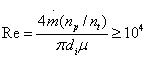 . (1.4)
where m, ρ and μ are mass flow rate, density and viscosity of tube side fluid. However, this is subject to allowable pressure drop in the tube side of the heat exchanger.