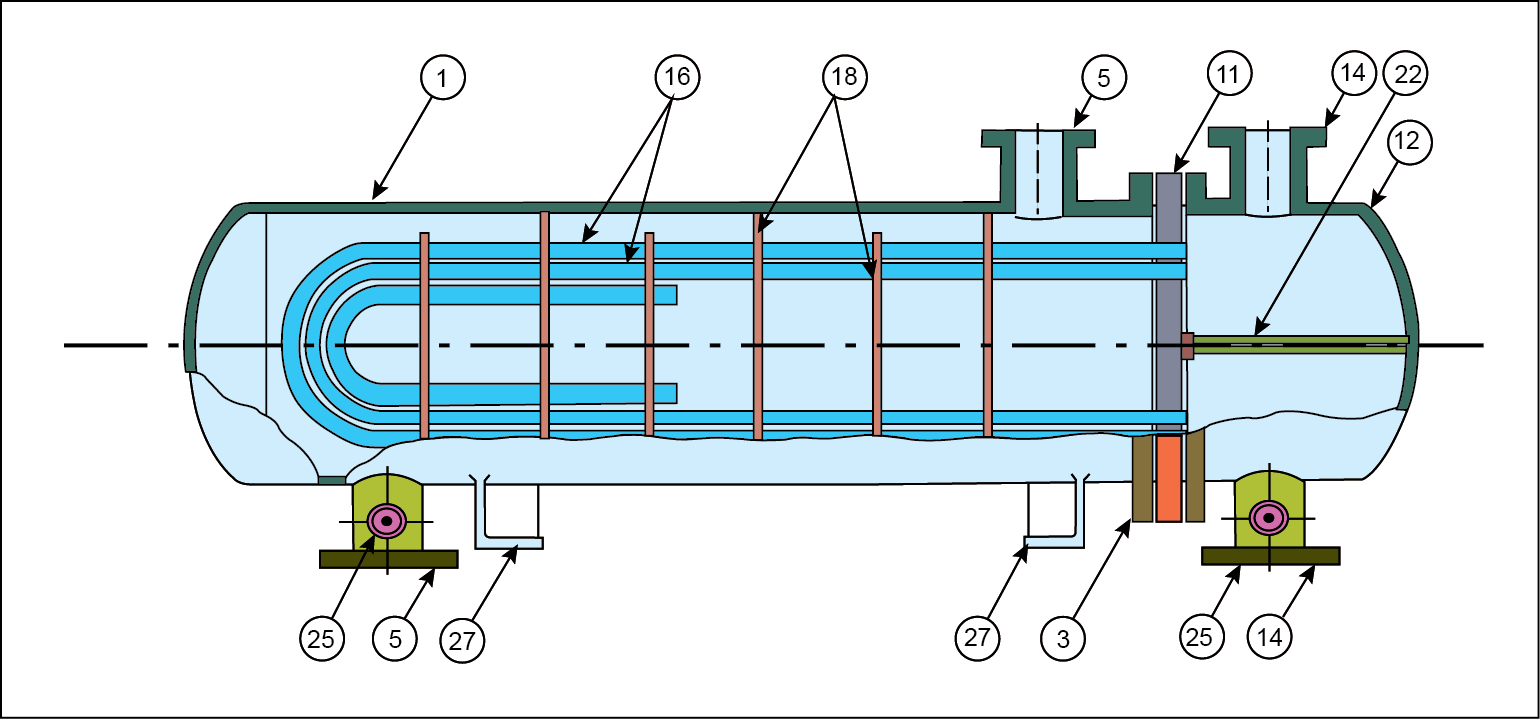
Figure 1.4. Removable U-tube heat exchanger [1] .
Typical parts and connections shown in Figures 1.2 , 1.3 and 1.4 ( IS: 4503-1967 ) are summarized below.
1. Shell |
16. Tubes (U-type) |
2. Shell cover |
17. Tie rods and spacers |
3. Shell flange (channel end) |
18. Transverse (or cross) baffles or support plates |
4. Shell flange (cover end) |
19. Longitudinal baffles |
5. Shell nozzle or branch |
20. Impingement baffles |
6. Floating tube sheet |
21. Floating head support |
7. Floating head cover |
22. Pass partition |
8. Floating head flange |
23. Vent connection |
9. Floating head gland |
24. Drain connection |
10. Floating head backing ring |
25. Instrument connection |
11. Stationary tube sheet |
26. Expansion bellows |
12. Channel or stationary head |
27. Support saddles |
13. Channel cover |
28. Lifting lugs |
14. Channel nozzle or branch |
29. Weir |
15. Tube (straight) |
30. Liquid level connection |