Working principle and Instrumentation
The instrument is called an X-ray diffractometer. In the diffractometer, an X-ray beam of a single wavelength is used to examine the specimens. By continuously changing the incident angle of the X-ray beam, a spectrum of diffraction intensity versus the angle between incident and diffraction beam is recorded.
The main components of diffractometer are
- X-ray Tube: the source of X Rays.
- Incident-beam optics: to condition the X-ray beam before it hits the sample
- Goniometer: the platform that holds and moves the sample, optics, detector, and/or tube
- Sample holder
- Receiving-side optics: to condition the X-ray beam after it has encountered the sample
- Detector: to count the number of X Rays scattered by the sample
The basic components of the diffractometer are shown in Fig 8. The ‘θ' is the angle between the X-ray source and the sample. whereas 2θ is the angle between the incident beam and the detector. The incident angle θ is always half of the detector angle 2θ. The basic function of a diffractometer is to detect X-ray diffraction from materials and to record the diffraction intensity as a function of the diffraction angle (2θ). The X-ray radiation generated by an X-ray tube passes through Soller slits which collimate the X-ray beam. The X-ray beam passing through the slits strikes the specimen. X-rays are diffracted by the specimen and form a convergent beam at the receiving slits before they enter a detector.
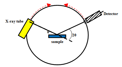
Fig. 2. Basic components of X-ray diffractometers
The diffracted X-ray beam passes through a monochromatic filter to suppress wavelengths other than Ka radiation and decrease any background radiation, before being received by the detector. The Ka radiation is generated by bombarding of target surface (Cu, Fe, Cr) by accelerated electrons. Most commonly a copper target is used generating Ka wave length of 0.154 nm.
Relative movements among the X-ray tube, specimen and the detector ensure the recording of diffraction intensity in a range of 2θ.
An instrument can be operated in two ways:
- tube is fixed, the sample and the detector rotates (THETA : 2-THETA arrangement)
- sample is fixed and the tube and the detector rotates (THETA:THETA arrangement)
Powder diffraction
A single crystal produces only one family of peaks in the diffraction pattern. A polycrystalline sample contains thousands of crystallites. Therefore, all possible diffraction peaks are observed. Powder diffraction is used for characterization of polycrystalline materials. The basic assumption of powder diffraction is that for every set of planes, there are statistically relevant number of crystallites that are properly oriented to diffract the incident beam. The diffraction pattern is the fingerprint of any crystalline phase. The position, intensity, shape and width of the diffraction lines give s information on the samples. Powder diffraction data consists of a record of photon intensity versus detector angle 2Ө. Diffraction data can be reduced to a list of peak positions and intensities. Each dhkl corresponds to a family of atomic planes (hkl). However, individual planes cannot be resolved by this method; this is a limitation of powder diffraction versus single crystal diffraction
Applications
Catalysts are extensively characterized by XRD technique.The major applications of XRD are discussed below.
1. Phase Identification
The catalysts are generally composed of mixture of several phases. The diffraction pattern for each phase is as unique as a fingerprint. Phases with the same chemical composition can have drastically different diffraction patterns. Phase identification is based on the comparison of the diffraction pattern of the specimen with that of pure reference phases or with a database. Databases such as the Powder Diffraction File (PDF) contain lists for thousands of crystalline phases. The PDF contains over 200,000 diffraction patterns. Modern computer programs can determine the phases present in a sample by quickly comparing the diffraction data to all of the patterns in the database. Various crystalline phases can be quantified based on the fact that each phase of the mixture gives its characteristic diffractogram independently of the others and the intensity depends on the amount present in the mixture. The intensity of the diffraction line (hkl) from a phase α is given by