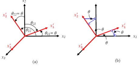
Let us derive the direction cosines for a transformation in a plane. Let the coordinate axes x1-x2 (that is, plane 1-2) are rotated about the third axis x3 by an angle  as shown in Figure 2.2. Thus, from the figure it is easy to see that as shown in Figure 2.2. Thus, from the figure it is easy to see that  . A careful observation of the figure shows that the angle between . A careful observation of the figure shows that the angle between  is not the same as the angle between is not the same as the angle between  . It means that the direction cosines . It means that the direction cosines  . .
| Figure 2.2 Transformation about x3 axis |
Now, we will find all the direction cosines. The list is given below.
The above can be written in a matrix form as
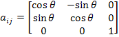 |
(2.1) |
The matrix of direction cosines given above in Eq. (2.1) is also written using short forms for 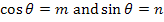 . Then Equation (2.1) becomes . Then Equation (2.1) becomes
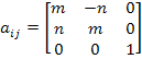 |
(2.2) |
Note: Some of the books and research articles also use 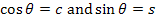 . .
Note: This matrix is also called Rotation Matrix.
Note: The above direction cosine matrix can be obtained from the relation between unrotated and rotated coordinates. For the transformation shown in Figure 2.2 (a) one can write this relation using the geometrical relations shown in Figure 2.2 (b) as
Now the direction cosines are given by the following relation:
Now we will use the direction cosines to transform a vector, a second order tensor and a fourth order tensor from initial coordinate (unprimed) system to a vector, a second order tensor and a fourth order tensor in final coordinate (primed) system.
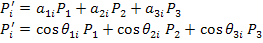
First, let us do it for a vector. Let  denote the components of a vector P in unprimed and primed coordinate axes. Then the components of this vector in rotated coordinate system are given in terms of components in unrotated coordinate system and corresponding direction cosines as denote the components of a vector P in unprimed and primed coordinate axes. Then the components of this vector in rotated coordinate system are given in terms of components in unrotated coordinate system and corresponding direction cosines as
 |
(2.3) |
Now, putting the direction cosines in terms of angles and summing over the repeated index j (=1, 2, 3) in Equation (2.3) we get
 |
(2.4) |
|