40.1 Drag reduction techniques
Imposed bluntness at the nose of the hypersonic vehicle is necessary to alleviate the oncoming heat load. However, increased wave drag is the immediate consequence of the forced bluntness. The required fuel of the propulsive vehicle increases due to a large drag force. It is also observed that a, marginal change in the drag force produces drastic change in the range of the missile or payload of the vehicle. Therefore, numerous wave drag reduction techniques are devised.
40.2 Aero-Spike Based Drag Reduction Studies
The idea of structural aerodynamic spike is to offer an effective passive means to reduce the wave drag. The spike recasts the original bow shock into a conical shock and induces a low pressure recirculation region, which together forms an aerodynamic configuration similar to that of a slender body ahead of blunt body. The schematic of the large angle blunt cone with aero-spike is shown in Fig. 40.1. The adverse pressure gradient incurred due to the presence of blunt body and friction offered by the spike jointly separate the flow near the stagnation region in the wake of the aerospike. The consequence of separation is the formation of a low pressure and low temperature recirculation region or separation bubble near the stagnation region. Presence of the low pressure and low energy flow ahead of the body reduces the wave drag. Separated flow reattaches at the blunt body and the location of this reattachment point depends on the spike length, spike configuration and freestream conditions. A reattachment shock appears at the reattachment point to turn the flow accordingly. Drag reduction for a blunt cone model using the aero-spike has been a topic of research from the last five to six decades. Numerical and experimental investigations have been carried out for a variety of objectives. Different lengths and geometries of spike, Reynolds number, Mach number and different test configurations have been considered as typical parameters during these studies.
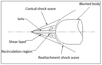
Fig.40.1. Typical Spiked configuration for drag reduction