34.2 Modifications in Shock Tunnel
Shock tunnels are preferred over the wind tunnel mainly for two reasons viz. cost of operation is low and flows with higher stagnation temperature can be simulated. However the higher stagnation temperature of the flow solely depends on the primary shock Mach number or stronger primary shock (Eq. 34.1). Hence higher shock speed is the prime requirement for simulation of flows with higher stagnation temperature. Higher shock speeds can be achieved by incorporating convergence from driver section to driven section or by a convergent divergent diaphragm mounting station. Moreover the strength of the primary shock can be increased with increase in driver to driven gas pressure ratio and temperature ratio as shown in Eq. 34.4.
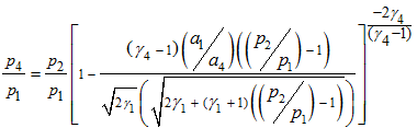 |
34.4 |
Operation of the shock tunnel with combustion driven shock tube (section 33.4) is one of the options for increase in driver to driven gas temperature ratio. The principle idea behind using combustion is with regard to driver gas heating. However there are numerous parallel ways investigated and reported in the literature. High enthalpy freestream can also be achieved in the test section by heating the driver gas of the shock tunnel by various methods viz. arc heating, shock heating and adiabatic compression of driver gas. Arc heating of the driver gas is achieved by installing electrodes in the driver section and string the arc across them. Thus generated arc deposits energy in the driver gas which in turn raises the driver gas temperature. The shock heating is carried out by using a double diaphragm shock tunnel. Schematic of the double diaphragm shock tunnel is as shown in Fig. 34.2. This operates like a conventional shock tunnel.
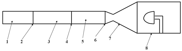
1. Primary Driver Section 2. Diaphragm 3. Main Driver Section 4.Diaphragm 5.Driven Section 6.Diaphragm 7.Nozzle 8.Test section and vacuum tank assembly
Fig. 34.2: Schematic of a typical double diaphragm shock tunnel.
This facility is same as that of shock tunnel. During the operation, all the diaphragms are mounted and required test gas is filled in the driven section. Low pressure is obtained in vacuum tank and driven gas pressure is set to the desired level. Main driver section is then filled with the main driver gas and pressure is noted. The primary driver section is then continuously filled with the driver gas. The driver gas filled in this section can be different from the one filled in the main driver section. Bursting of the diaphragm at station 2 (Fig. 34.2) starts the operation of the tunnel by initiating the shock in the main driver section. This shock increases the driver pressure and also heats it. Reflection of this shock further raises the driver pressure and temperature and bursts the diaphragm at station 4 (Fig. 34.2). Thus generated primary shock travels in the driven section. Further operation of the tunnel is same as that of the shock tunnel. This shock tunnel working methodology increases the primary shock strength and hence the nozzle supply conditions which makes this tunnel to be useful for wider range high enthalpy applications.