34.1 Shock Tunnel
A typical shock tunnel is as shown in Fig. 34.1. It is very much clear from this figure that, the shock tunnel is an obvious extension of shock tube. A conventional shock tunnel is comprised of three sections viz. shock tube, nozzle and test section dump tank assembly. Nozzle, test section and dump tank together are called as wind tunnel part of the shock tunnel since these parts are similar to that seen in wind tunnel. The driven section end of the shock tube is kept open and connected to the convergent divergent nozzle. The convergent part of the nozzle is provided with minimal length so as to provide the shock reflection. The other end of the nozzle is connected to the test section and dump tank assembly. During the experiment, diaphragm is installed between driver and driven sections of the shock tube. A paper diaphragm is put between the driven section and nozzle. Desired driven or test gas is filled in the driven section and pressure is adjusted using the vacuum pump connected to it. Lowest possible pressure is attainted and then maintained in the test section and dump tank assembly where instrumented test model is mounted. Driver section is then filled with the driver gas till the metallic diaphragm ruptures. Usual shock tube operation persist post diaphragm rupture. The reflected shock provides the high pressure and high temperature test gas at the entry to the nozzle. Further expansion of the test gas in the nozzle attains desired freestream conditions in the test section.
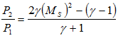
Pressure sensors mounted in the driven section give the pressure rise across the primary shock. Primary shock Mach number can be calculated through measured pressure and known specific heat ratio of the test gas using shock tube relations as,
 |
34.1 |
Here P1 and P2 are the pressure ahead and behind the moving primary shock, γ is the specific heat ratio of driver gas and Ms is the primary shock Mach number.
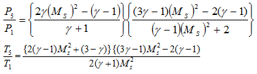
Thus obtained shock Mach number can be used to calculate the pressure and temperature behind the reflected shock as,
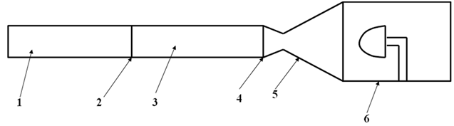
1. Driver Section 2. Diaphragm 3. Driven Section 4.Diaphragm 5.Nozzle 6.Test section and vacuum tank assembly
Fig. 34.1: Schematic of a typical Shock Tunnel
 |
34.2
34.3 |
Here P5 and T5 are the pressure and temperature behind the reflected shock. These properties are necessarily the stagnation properties of the test gas. Flow parameters in the test section can be estimated as discussed in section 32.3. More commonly used method is measurement of pitot pressure (total pressure behind the normal shock) in the test section.
For impulsive type facilities, such as shock tunnels, where extremely high throat heat transfer rate is expected for a short time, it is advisable to provide cooling for the throats. Without any cooling, the throat surface temperature may reach the melting point during a tunnel run and may experience severe oxidation if air is used as the working fluid. Both of these lead to throat erosion, alteration of the throat shape and flow contamination. Therefore, materials such as Tungsten, beryllium oxide may be used to overcome the melting effect in such situations.