32.3. Flow Parameter Estimations for a Wind Tunnel.
Following techniques can be used to estimate the hypersonic flow parameters in the test section when the wind tunnel is used to simulate the hypersonic Mach number and corresponding Reynolds number.
1. Measurement of Stagnation Pressures: Measure stagnation pressure and stagnation temperature in the settling chamber which is the total pressure ahead of the shock. During the experiments measure the stagnation pressure in the test section using the pitot tube. Ratio of these measured total pressures for assumed constant specific heat ratio provides the freestream Mach number using normal shock relations as given in Eq. 32.1.
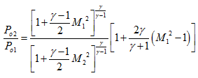 |
32.1 |
Thus calculated Mach number and measured total temperature can then be used to evaluate the static temperature in the test section using Eq. 32.2.
32.2 |
Hence freestream velocity, density and other parameters are then obvious from these calculations.
2. Measurement of Freestream Stagnation and Static Pressures: Measure stagnation pressure and stagnation temperature in the settling chamber which is the total pressure ahead of the shock. During the experiments, measure the static pressure in the test section using the pressure sensor mounted on a flat plate which experiences hypersonic flow at zero degree angle of attack. Ratio of the measured freestream total and static pressures along with the assumed constant specific heat ratio provide the freestream Mach number using isentropic relations.
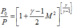 |
32.3 |
Thus calculated Mach number and measured total temperature can then be used to evaluate the static temperature in the test section. Hence freestream velocity, density and other parameters are then obvious from these calculations.
3. Measurement of Freestream Stagnation and Static behind the shock: Measure stagnation pressure and stagnation temperature in the settling chamber which is the total pressure ahead of the shock. During the experiments, measure the static pressure in the test section using the pressure sensor mounted on a flat plate which experiences hypersonic flow at any non-zero degree angle of attack which has the attached shock solution for the given freestream Mach number. Initial guess Mach number of the test gas can be predicted using area ratio of the convergent divergent nozzle of the tunnel.
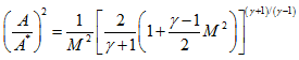 |
32.4 |
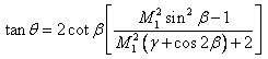
The angle of attack of the plate is chosen using this initial guess Mach number. Ratio of the measured freestream total pressure and static pressures behind the oblique shock along with the assumed constant specific heat ratio provide the freestream Mach number using oblique shock relations. Thus calculated Mach number and measured total temperature can then be used to evaluate the static temperature in the test section. Hence freestream velocity, density and other parameters are then obvious from these calculations.
4. Flow Visualisation for attached oblique shock: Freestream conditions can even be estimated using flow visualisation. For this method, a flat plate has to be mounted in the test section at an angle of attack for which an attached shock solution is expected. Stagnation pressure and temperature of the freestream are to be monitored in the settling chamber. Oblique shock angle will be visualised during the flow visualisation experiments. Known angle of attack of the plate and the oblique shock angle can be used to find out the freestream Mach number under the assumption of constant specific heat ratio using oblique shock relation
Thus calculated Mach number and measured total temperature can then be used to evaluate the static temperature in the test section. Hence freestream velocity, density and other parameters are then obvious from these calculations.