32.1 Nitrogen Wind Tunnel
It is a blow-down wind tunnel operated with high pressure Nitrogen gas. Hence the arrangement of this tunnel is same as that of a blow-down wind tunnel (Fig. 32.1). The high pressure Nitrogen gas is initially heated by a graphite resistance heater contained within a pressure vessel and then allowed to expand through the nozzle. Experimental duration in these tunnels is in the range of 1 to 4 seconds. Nitrogen wind tunnels also operate between two temperature limits discussed herein. The lower limit on temperature is essentially to avoid condensation effects in the test section, and the upper limit on the temperature is necessarily governed by the heater. Two servo-systems are installed for two reasons viz. controlling the gas flow to maintain a constant stagnation pressure and ensuring a constant current through the heater which effectively controls the stagnation temperature.
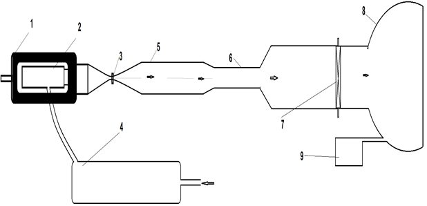
1.High pressure vessel 2.Graphite resistance heater 3.Nozzle with water cooling at throat 4.Multistage compressor 5.Test section 6.Diffuser Second throat 7.Valve 8.Vacuum Chamber 9.Vacuum pump
Fig 32.1: Schematic drawing of Nitrogen wind tunnel circuit
32.2 Continuous Tunnel or Arc Jet Wind Tunnels
This wind tunnel type is used to simulate the hypersonic, hypervelocity and high enthalpy airflows that are experienced by space flights during atmospheric re-entry and also to provide the insight for real gas effect aerodynamics for design of thermal protection system. This tunnel is from the realm of blow-down tunnel where heating of the test gas is carried out using electric heaters. These heaters are placed in the pressure vessel containing high pressure test gas. Copper electrodes with water cooling arrangement are used to enhance the life of the electrode. The high pressure electrically heated test gas is then passed through the convergent divergent nozzle to attain the required Mach number in the test section.
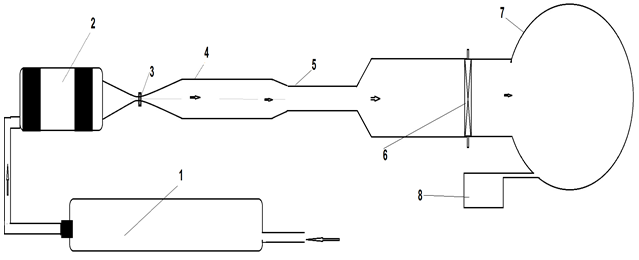
1. Multistage compressor 2. Arc-jet heater 3.Nozzle with water cooling at throat 4.Test section 5.Diffuser Second throat 6.Valve 7.Vacuum Chamber 8.Vacuum pump
Fig. 32.2: Schematic drawing of Arc-Jet wind tunnel circuit