Phase
and Phase difference in simple harmonic motion : In
general the solution of a simple harmonic equation
is
As mentioned earlier A is known as the amplitude
and  as
the phase. as
the phase.  is
a constant depending on the initial conditions
and we call it the phase constant. Let us now
see how does the motion look for different values
of the phase constant is
a constant depending on the initial conditions
and we call it the phase constant. Let us now
see how does the motion look for different values
of the phase constant  .
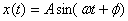
The displacement versus time plots for different
signs of the phase constant are shown in figure
10. .
The displacement versus time plots for different
signs of the phase constant are shown in figure
10.
For Φ > 0 the motion
at t = 0 begin at a value or phase angle that it
would have slightly later in the  case.
On the other hand, for Φ < 0
the motion is such that a particular displacement
for the case.
On the other hand, for Φ < 0
the motion is such that a particular displacement
for the  case
is reached at a later time. The motion lags behind
the case
is reached at a later time. The motion lags behind
the  motion.
I leave it for you to figure out yourself how
the corresponding velocities are related. motion.
I leave it for you to figure out yourself how
the corresponding velocities are related.
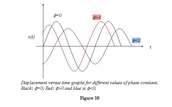
Let us now at the special case of  .
In this case I get .
In this case I get
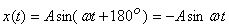
and for 
So you see that a phase difference of 180o,
whether position or negative, means the same thing.
I would like you to plot the displacement versus
time graph for these particular cases. For the phases
in between you should see for yourself how the displacements
at t = 0 are different from  case. case.
A good way of visualizing the simple harmonic motion is
the phasor or vector diagram. I discuss that next.
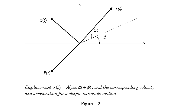
Phasor or vector diagram: A nice
geometric way of looking at various quantities in
a simple harmonic motion is the vector or a phasor
diagram. You may have seen it in your 12th grade
while studying AC circuits. Let me show you how we
represent 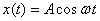 in
a geometric way. You see that displacement in
this case is the x component of a vector
making an angle ωt from the x-axis.
Thus the displacement is represented as shown in
figure 11. The motion described by in
a geometric way. You see that displacement in
this case is the x component of a vector
making an angle ωt from the x-axis.
Thus the displacement is represented as shown in
figure 11. The motion described by  is
thus given by the projection of a vector of length A,
rotating counterclockwise at a rate ω,
on the x-axis. is
thus given by the projection of a vector of length A,
rotating counterclockwise at a rate ω,
on the x-axis.
Let us now see how the velocity  and
the acceleration will be represented in this
scheme? The velocity and acceleration are given as and
the acceleration will be represented in this
scheme? The velocity and acceleration are given as
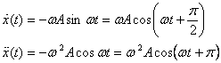
The displacement, velocity and acceleration are shown
in the phasor diagram in figure 12. A general
feature that we observe from this phase diagram is
that the velocity vector is always  ahead
(measuring counterclockwise) of the displacement
vector and the acceleration vector is at π (ahead
or behind?) the displacement. ahead
(measuring counterclockwise) of the displacement
vector and the acceleration vector is at π (ahead
or behind?) the displacement.
So far we have discussed the simple case of  .
What about the general case of .
What about the general case of 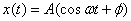 .
This is also equally simple. All we have to do
is keep the initial position of the vector at t
= 0 at
an angle Φ from the x-axis and start
rotating it from there. The velocity vector and
the acceleration vector are then going to be
given at .
This is also equally simple. All we have to do
is keep the initial position of the vector at t
= 0 at
an angle Φ from the x-axis and start
rotating it from there. The velocity vector and
the acceleration vector are then going to be
given at  and
π from it, as discussed above. This is shown
in figure 13. and
π from it, as discussed above. This is shown
in figure 13.
Recall that in the middle of this lecture I had solved
a spring-mass problem with different initial conditions.
I would like you to make the phasor diagram to represent
the motion of the mass in many different situations like
those considered above. Do not solve for x(t) to start
with, just make the phasor diagram directly to see if
you have got a feel for motion under different conditions.
Finally in this lecture I look at the energy of a system
performing simple harmonic motion. The potential energy U(x) and
the kinetic energies T are
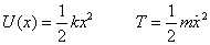
The total energy E is of course a sum of
the two. With  this
gives this
gives
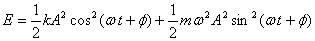
Since  ,
we get ,
we get

Thus the energy depends on the square of the amplitude.
This makes sense because if I stretch a spring
by A,
the energy stored in it is  .
On releasing the mass it performs oscillations
of amplitude A. Thus you see that amplitude A
immediately implies a total energy given above. .
On releasing the mass it performs oscillations
of amplitude A. Thus you see that amplitude A
immediately implies a total energy given above.
I have now set up all the basic concepts of simple harmonic
motion. In the coming lectures I will introduce damping
in the system and see how it evolves.
|