A network of passive elements and sources is a circuit.
Analysis: To determine currents or voltages in various
elements (effects) due to various sources (cause).
In circuit 4.1 ![]() all the time.
all the time.
Expected that all current (voltage) in (across) the elements is
constant.
Inductor:
 |
(4.1) |
![]() implies
implies ![]() constant.
constant.
Hence ![]()
Inductors act as a short cicuit for DC inputs. This would not be the
case if I put a switch across a source.
Capacitor:
 |
(4.2) |
as
![]() (expected),
(expected), ![]() .
.
Thus capacitor acts as open circuit for DC analysis.
The resultant circuit will be as shown in Fig.4.2.
Analysis: To find currents in all branches, voltage across
all branches.
We can use Kirchoff's law (voltage and current). For as many
independent equations as number of unknown variables.
Solve the simultaneous equations, and get the result.
![]() Voltage drop from 'a' to 'b'. Therefore,
Voltage drop from 'a' to 'b'. Therefore,
![]()
![]() Current in branch ab in the direction from 'a' to 'b'. Here
Current in branch ab in the direction from 'a' to 'b'. Here
![]() .
.
Hence:
Note: In a circuit with ![]() nodes, the number of branches
nodes, the number of branches ![]() will
alwasy be
will
alwasy be ![]() , where
, where ![]() are maximum number of independent closed
paths possible in the circuit.
are maximum number of independent closed
paths possible in the circuit.
Hence, we can always form ![]() equations using Ohm's law,
equations using Ohm's law, ![]() equations
using KCL,
equations
using KCL, ![]() equations using KVL. Hence in total
equations using KVL. Hence in total ![]() equations can be
formed, which are sufficient to solve for
equations can be
formed, which are sufficient to solve for ![]() variables (voltage and
current in each branch).
variables (voltage and
current in each branch).
Can we simplify the situation? Loop currents method: We do away with branch currents and define loop currents. The branch currents can be written in terms of loop currents once all the loop currents passing through the branch and their directions are known. The branch voltages can always be written using Ohm's law and branch current written in terms of loop currents. So now our objective is to find loop currents. For this we choose maximum number of independent loops (Fig.4.3) and apply KVL in them.
If ![]() and
and ![]() are known, voltages across all elements can be
found.
are known, voltages across all elements can be
found.
Make two independent equations:
For loop abef
| (4.3) | |||
| (4.4) |
For loop bcde:
| (4.5) | |||
| (4.6) |
Use any technique to solve these (such as using matrices). We get:
 |
(4.7) | ||
 |
(4.8) |
Nodal Voltage Method
Considering Fig.4.4.
Independent Nodes: One of the nodes in circuit need to be
considered as reference node. Hence its node potential is zero. For
other nodes, nodal voltage is potential differetial w.r.t. to reference
node. The nodes are called independent nodes. In general for ![]() node
network,
node
network, ![]() nodes will be independent.
nodes will be independent.
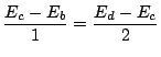
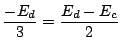
At node b:
![]() .
.
Similarly, other equations are:
 |
(4.9) | ||
 |
(4.10) | ||
| (4.11) | |||
 |
(4.12) | ||
 |
(4.13) | ||
 |
(4.14) |
Current Sources in Loop Current Analysis
Using KVL for loop 1 in Fig.4.5:
| (4.15) |
| (4.16) |
| (4.17) |
The first and the third equation can be combined for taking care of
![]() . This can be done by making superloop for writing KVL.
. This can be done by making superloop for writing KVL.
Graph
For analysing circuits efficiently.
Loop current method
One can form a spanning tree from graph such that current sources are in links (Those elements which do not form part of the tree). Each link when added to the tree gives a loop.
All voltage sources should be kept in branches of tree. For example,
refer to the following two figures (Fig.4.6 , Fig.4.7)
Node voltages
In the above figure, ![]() . There are five unknown node voltages in the above circuit, namely,
. There are five unknown node voltages in the above circuit, namely, ![]() ,
, ![]() ,
, ![]() ,
, ![]() and
and ![]() . Correspondingly, we have five equations. Note that we can merge
. Correspondingly, we have five equations. Note that we can merge ![]() into one supernode
into one supernode
The second equation follows from looking at node ![]() , while the third one from doing the same at node
, while the third one from doing the same at node ![]() .
.
![\includegraphics[width=3.0in]{lec3figs/1.eps}](img129.png)
![\includegraphics[width=3.0in]{lec3figs/2.eps}](img138.png)
![\includegraphics[width=3.0in]{lec3figs/3.eps}](img160.png)
![\includegraphics[width=3.0in]{lec3figs/4.eps}](img169.png)
![\includegraphics[width=3.0in]{lec3figs/5.eps}](img178.png)
![\includegraphics[width=3.0in]{lec3figs/6.eps}](img183.png)
![\includegraphics[width=3.0in]{lec3figs/7.eps}](img184.png)
![\includegraphics[width=3.0in]{lec3figs/8.eps}](img185.png)