While in the Half wave rectification, we got an output only in one of the half cycles, in the full wave, we get it for both the half cycles. This is achieved through the circuit shown below.
This is achieved by the use of two diodes instead of one as now, one of the two diodes remains in conduction in both of the half cycles. Note that we require a center tapped transformer to give us two ![]() shifted sinusoids so that exactly one of the waveforms is positive at one time.
shifted sinusoids so that exactly one of the waveforms is positive at one time.
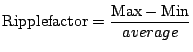
As the output is not the desired pure d.c., we introduce a measure of the quality of the output known as the Ripple Factor defined as:
 |
|||
 |
|||
 |
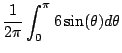
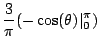
For the full wave rectifier, similarly we can calculate the average voltage to be
![]() volts. In both the cases, the difference of maximum and minimum voltages is
volts. In both the cases, the difference of maximum and minimum voltages is ![]() V. Therefore, ripple factor
V. Therefore, ripple factor ![]()
![\includegraphics[width=3.5in]{lec8figs/11.eps}](img596.png)
![\includegraphics[width=3.5in]{lec8figs/12.eps}](img597.png)
![\includegraphics[width=3.5in]{lec8figs/14.eps}](img600.png)