Design of Zener regulator circuit:
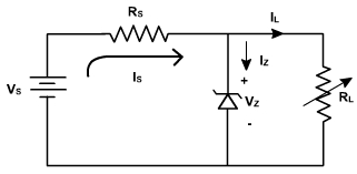
A zenere regulator circuit is shown in fig. 6. The varying load current is represented by a variable load resistance RL.
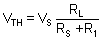
The zener will work in the breakdown region only if the Thevenin voltage across zener is more than VZ .
If zener is operating in breakdown region, the current through RS is given by
Fig. 6
and load current
Is= Iz + ILThe circuit is designed such that the diode always operates in the breakdown region and the voltage VZ across it remains fairly constant even though the current IZ through it vary considerably.
If the load IL should increase, the current IZ should decrease by the same percentage in order to maintain load current constant Is. This keeps the voltage drop across Rs constant and hence the output voltage.
If the input voltage should increase, the zener diode passes a larger current, that extra voltage is dropped across the resistance Rs. If input voltage falls, the current IZ falls such that VZ is constant.
In the practical application the source voltage, vs, varies and the load current also varies. The design challenge is to choose a value of Rs which permits the diode to maintain a relatively constant output voltage, even when the input source voltage varies and the load current also varies.
We now analyze the circuit to determine the proper choice of Rs. For the circuit shown in figure,
(E-1)
(E-2)
The variable quantities in Equation (E-2) are vZ and iL. In order to assure that the diode remains in the constant voltage (breakdown) region, we examine the two extremes of input/output conditions, as follows:
- The current through the diode, iZ, is a minimum (IZ min) when the load current, iL is maximum (IL max) and the source voltage, vs is minimum (Vs min).
- The current through the diode, iZ, is a maximum (IZ max) when the load current, iL, is minmum (iL min) and the source voltage vsis minimum(Vs max).
When these characteristics of the two extremes are inserted into Equation (E-1),
we find
(E-3)
(E-4)
In a practical problem, we know the range of input voltages, the range of output load currents, and the desired Zener voltage. Equation (E-4) thus represents one equation in two unknowns, the maximum and minimum Zener current. A second equation is found from the characteristic of zener. To avoid the non-constant portion of the characteristic curve, we use an accepted rule of thumb that the minimum Zener current should be 0.1 times the maximum (i.e., 10%), that is,
(E-5)
Solving the equations E-4 and E-5, we get,
(E-6)
Now that we can solve for the maximum Zener current, the value of Rs, is calculated from Equation (E-3).
Zener diodes are manufactured with breakdown voltages VZ in the range of a few volts to a few hundred volts. The manufacturer specifies the maximum power the diode can dissipate. For example, a 1W, 10 V zener can operate safely at currents up to 100mA.