Applications of diode:
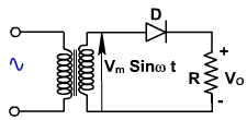
Half wave Rectifier:
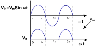
The single phase half wave rectifier is shown in fig. 8.
Fig. 8 Fig. 9 In positive half cycle, D is forward biased and conducts. Thus the output voltage is same as the input voltage. In the negative half cycle, D is reverse biased, and therefore output voltage is zero. The output voltage waveform is shown in fig. 9.
The average output voltage of the rectifier is given by
The average output current is given by
When the diode is reverse biased, entire transformer voltage appears across the diode. The maximum voltage across the diode is Vm. The diode must be capable to withstand this voltage. Therefore PIV half wave rating of diode should be equal to Vm in case of single-phase rectifiers. The average current rating must be greater than Iavg
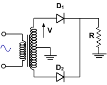
Full Wave Rectifier:
A single phase full wave rectifier using center tap transformer is shown in fig. 10. It supplies current in both half cycles of the input voltage.
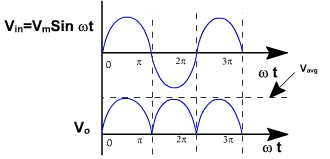
Fig. 10 Fig. 11 In the first half cycle D1 is forward biased and conducts. But D2 is reverse biased and does not conduct. In the second half cycle D2 is forward biased, and conducts and D1 is reverse biased. It is also called 2 pulse midpoint converter because it supplies current in both the half cycles. The output voltage waveform is shown in fig. 11.
The average output voltage is given by
and the average load current is given by
When D1 conducts, then full secondary voltage appears across D2, therefore PIV rating of the diode should be 2 Vm.