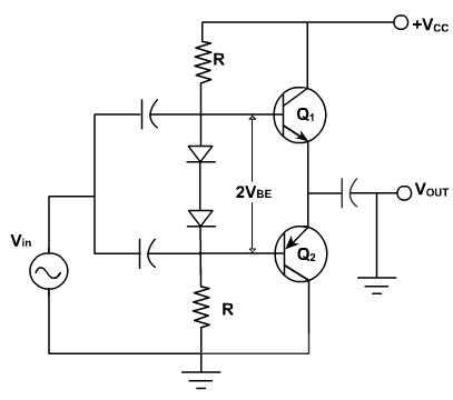
Biasing a class B amplifier:
In class B amplifier, two complement any transistors are required. Because of the series connection, each transistor drops half the supply voltage. To avoid cross over distortion, the Q-point slightly above cut off, with the correct VBE somewhere between 0.6 and 0.7.
If there is an increase in VBE by few mV it produces 10 times as much emitter current. Because of this it is difficult to find standard resistors that can produce the correct VBE and it needs an adjustable resistor.
The biasing does not solve thermal instability problem. Because for a given collector current, VBE requirement decreases by 2 mV per degree rise in temperature. The voltage divider produces a stiff drive for each diode. Therefore as the temperature increases, the fixed voltage on each emitter diode forces the collector current to increase and this gives rise to thermal run away. When the temperature increases collector current increases, and this is equivalent to Q-point moving up along the vertical dc load line. As the Q-point moves toward higher collector currents, the temperature of the transistor increases further reducing the required V BE .
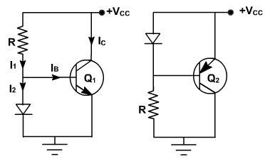
Fig. 3
One way to avoid thermal run away is to use diode bias. It is based on the concept of current mirror as shown in fig. 3, the base current is much smaller than the current through the resistor and diode. For this reason, I1 and I2 are approximately equal. If the diode curve is identical to the VBE curve of the transistor (VBE , IE ). The diode current equals the emitter and also collector current. Therefore I1 is nearly equal to IC.
I1 = I C .
The collector current is set by controlling the resistor current. This is called a current mirror.
Similarly, pnp transistor can be used as a current mirror. If the VBE curve of the transistor matches the diode curve, the collector equals the resistor current.
Diode bias of class B push pull emitter follower relies on two current mirrors as shown in fig. 4.
Fig. 4
The upper half is an npn current mirror, and the lower half is a pnp current mirror as shown in fig. 4. For diode bias to be immune to changes in temperature, the diode curve must match the VBE curves of the transistor over a wide temperature range. This is easily done in ICs .