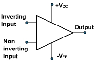
The symbolic diagram of an OPAMP is shown in fig. 1.
741c is most commonly used OPAMP available in IC package. It is an 8-pin DIP chip.
Parameters of OPAMP:
The various important parameters of OPAMP are follows:
1.Input Offset Voltage:
|
Fig. 2 |
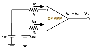
2. Input offset Current:
The input offset current Iio is the difference between the currents into inverting and non-inverting terminals of a balanced amplifier.
Iio = | IB1 IB2 |
The Iio for the 741C is 200nA maximum. As the matching between two input terminals is improved, the difference between IB1 and IB2 becomes smaller, i.e. the Iio value decreases further.For a precision OPAMP 741C, Iio is 6 nA
3.Input Bias Current:
The input bias current IB is the average of the current entering the input terminals of a balanced amplifier i.e.
IB = (IB1 + IB2 ) / 2
For 741C IB(max) = 700 nA and for precision 741C IB = ± 7 nA
4. Differential Input Resistance: (Ri)
Ri is the equivalent resistance that can be measured at either the inverting or non-inverting input terminal with the other terminal grounded. For the 741C the input resistance is relatively high 2 MΩ. For some OPAMP it may be up to 1000 G ohm.
5. Input Capacitance: (Ci)
Ci is the equivalent capacitance that can be measured at either the inverting and noninverting terminal with the other terminal connected to ground. A typical value of Ci is 1.4 pf for the 741C.
6. Offset Voltage Adjustment Range:
741 OPAMP have offset voltage null capability. Pins 1 and 5 are marked offset null for this purpose. It can be done by connecting 10 K ohm pot between 1 and 5 as shown in fig. 3.
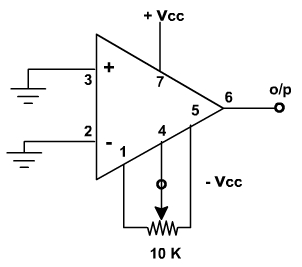
Fig. 3
By varying the potentiometer, output offset voltage (with inputs grounded) can be reduced to zero volts. Thus the offset voltage adjustment range is the range through which the input offset voltage can be adjusted by varying 10 K pot. For the 741C the offset voltage adjustment range is ± 15 mV.