The operation amplifier:
An operational amplifier is a direct coupled high gain amplifier consisting of one or more differential (OPAMP) amplifiers and followed by a level translator and an output stage. An operational amplifier is available as a single integrated circuit package.
The block diagram of OPAMP is shown in fig. 1.
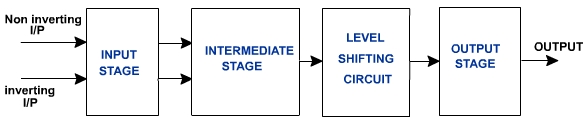
Fig. 1
The input stage is a dual input balanced output differential amplifier. This stage provides most of the voltage gain of the amplifier and also establishes the input resistance of the OPAMP.The intermediate stage of OPAMP is another differential amplifier which is driven by the output of the first stage. This is usually dual input unbalanced output.
Because direct coupling is used, the dc voltage level at the output of intermediate stage is well above ground potential. Therefore level shifting circuit is used to shift the dc level at the output downward to zero with respect to ground. The output stage is generally a push pull complementary amplifier. The output stage increases the output voltage swing and raises the current supplying capability of the OPAMP. It also provides low output resistance.
Level Translator:
|
Fig. 2 |
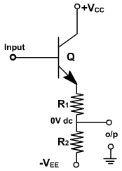
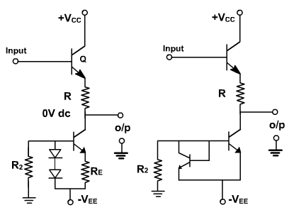
Fig. 3
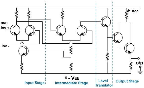
Fig. 4, shows a complete OPAMP circuit having input different amplifiers with balanced output, intermediate stage with unbalanced output, level shifter and an output amplifier.
Fig. 4