Constant Current Bias:
In the dc analysis of differential amplifier, we have seen that the emitter current IE depends upon the value of bdc. To make operating point stable IE current should be constant irrespective value of bdc.
For constant IE, RE should be very large. This also increases the value of CMRR but if RE value is increased to very large value, IE (quiescent operating current) decreases. To maintain same value of IE, the emitter supply VEE must be increased. To get very high value of resistance RE and constant IE, current, current bias is used.
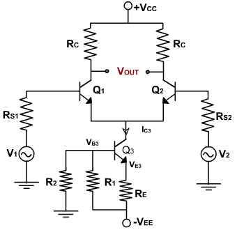
Figure 5.1
Fig. 1, shows the dual input balanced output differential amplifier using a constant current bias. The resistance RE is replace by constant current transistor Q3. The dc collector current in Q3 is established by R1, R2, & RE.
Applying the voltage divider rule, the voltage at the base of Q3 is
Because the two halves of the differential amplifiers are symmetrical, each has half of the current IC3.
The collector current, IC3 in transistor Q3 is fixed because no signal is injected into either the emitter or the base of Q3.
Besides supplying constant emitter current, the constant current bias also provides a very high source resistance since the ac equivalent or the dc source is ideally an open circuit. Therefore, all the performance equations obtained for differential amplifier using emitter bias are also valid.
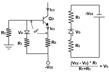
As seen in IE expressions, the current depends upon VBE3. If temperature changes, VBE changes and current IE also changes. To improve thermal stability, a diode is placed in series with resistance R1as shown in fig. 2.
This helps to hold the current IE3 constant even though the temperature changes. Applying KVL to the base circuit of Q3.Fig. 2
Therefore, the current IE3 is constant and independent of temperature because of the added diode D. Without D the current would vary with temperature because VBE3 decreases approximately by 2mV/° C. The diode has same temperature dependence and hence the two variations cancel each other and IE3 does not vary appreciably with temperature. Since the cut in voltage VD of diode approximately the same value as the base to emitter voltage VBE3 of a transistor the above condition cannot be satisfied with one diode. Hence two diodes are used in series for VD. In this case the common mode gain reduces to zero.