Example 2
|
Fig. 2 |
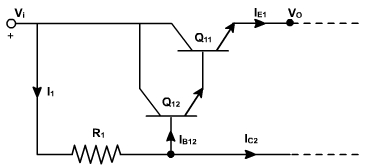
We now select I2≈ 0.65 mA; R1 is calculated as follows:
where,
The extreme values of I1 occurs when Vi is at its extremes. The minimum I1 is 0.65mA (as indicated above), while the maximum is
The variation in I1 is 1.5 - 0.65 = 0.85mA.
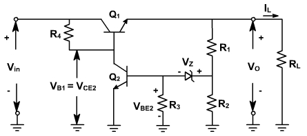
Example - 3
In the regulator shown in fig. 3 R1 = 50KΩ, R2 = 43.75KΩ and VZ = 6.3V. If the 15 V output drops 0.1 V, find the change in VBE2 that results.
Fig. 3
Solution:
When VO = 15 V,
Therefore, VBE2 = V2 - VZ = 7 V - 6.3 V = 0.7 V. When VO = 15 V - 0.1 V = 14.9 V, V2 becomes
Therefore,