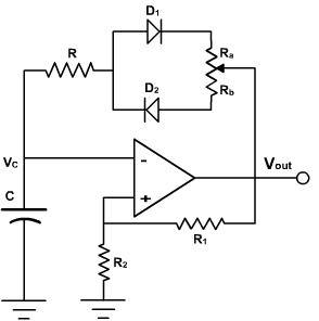
The duty cycle of the output wave can be changed replacing the resistance R by another circuit consisting of variable resistance and two diodes D1 and D2 as shown in fig. 3.
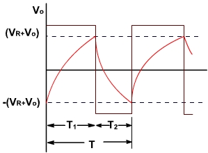
When the output is positive then D2 conducts and D1 is OFF. The total feedback resistance becomes Rb+R and charging voltage is reduced by VD. During the interval when the output is negative then D1 conducts and D2 is OFF. The charging resistance becomes R+Ra. The total charging and reverse charging period is decided by total resistance (2 R + Ra + Rb) = constant. Therefore frequency will remain constant but duty cycle changes. The capacitor voltage and output voltage of the oscillator are shown in fig. 4.
The duty cycle is given by
By varying Ra and Rb the duty cycle can be charged keeping frequency constant.
Example - 2
Characterize the astable mulitvibrator shown in fig. 5. Establish the frequency range.
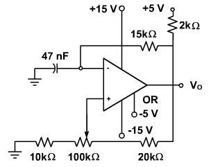
Fig. 5
Solution:
By observing the way the output section is connected, we conclude that the output voltage oscillates between VL = - 5V and VH = + 5V.
To calculate the oscillation frequency range, two extreme values for R1 and R2 are used. Thus, when the wiper of the potentiometer is at its leftmost position, R1 = 120 kΩ and R2 = 10 kΩ. At the other extreme, R1 = 20 kΩ and R2 =110 kΩ.
Substituting the values of R1 and R2 in the expression of T, we obtain the two extreme values of T, i.e., Tmin and Tmax
.
Therefore,
fmin = 285 Hz and fmax = 4.6 kHz