Example - 1
Design a voltage level detector with noise immunity that indicates when an input signal crosses the nominal threshold of 2.5 V. The output is to switch from high to low when the signal crosses the threshold in the positive direction, and vice versa. Noise level expected is 0.2 VPP, maximum. Assume the output levels are VH = 10 V and VL = 0V.
Solution:
For the triggering action required an inverting configuration is required. Let the hysteresis voltage be 20% larger that the maximum pp noise voltage, that is, Vhys = 0.24V.
Thus, the upper and lower trigger level voltages are -2.5 ± 0.12, or
UTP = 2.38 V and LTP = -2.62 V
Since the output levels are VH and VL instead of +Vsat and Vsat, therefore, hysteresis voltage is given by
or
andThe reference voltage V R can be obtained from the expression of LTP.
Given that VL = 0, and LTP= -262, we obtain
VR = (1 + R2 / R1) LTP = (1 + 1 / 40.7) (-2.62) = - 2.68 V
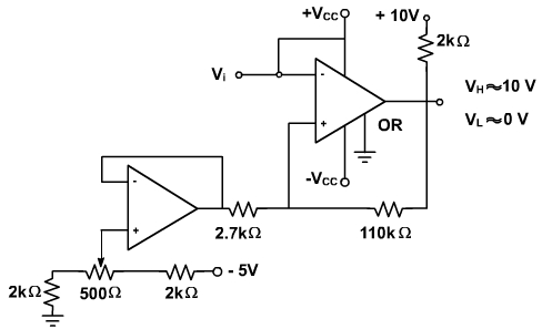
We can select any values for R2 and R1 that satisfy the ratio of 40.7. It is a good practice to have more than 100 kΩ for the sum of R1 and R2 and 1 kΩ to 3kΩ for the pull up resistor on the output. The circuit shown in fig. 7 shows a possible final design. The potentiometer serves as a fine adjustment for VR, while the voltage follower makes VR to appear as an almost ideal voltage source.
Fig. 7