Active Full Wave Rectifier:
Method 1:
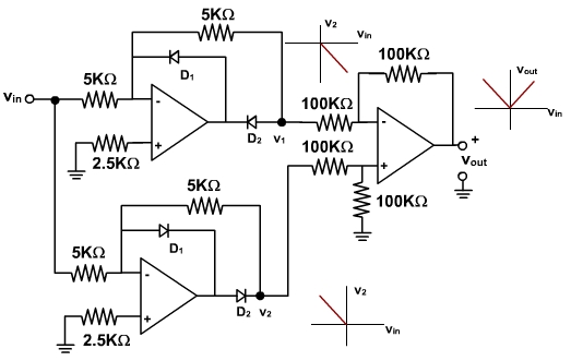
A full wave rectifier, or magnitude operator, produces an output which is the absolute value, or magnitude, of the input signal waveform. One method of accomplishing full wave rectification is to use two half wave rectifiers. One of these operates on the positive portion of the input and the second operates on the negative portion. The outputs are summed with proper polarites. Fig. 1 illustrates one such configuration. Note that the resistive network attached to the ouput summing opamp is composed of resistors of higher value than those attached to the opamp that generates v1. This is necessary since for negative vin, v2 follows the curve shown above the node labled v2. That is, as the input increases in a negative direction, v2 increases in a positive direction. Since the input impedance to the non-inverting terminal of the summing opamp is high, the voltage, v+ is simply one half of v2 (i.e., the two 100KΩ resistors form a voltage divider). The voltage at the negative summing terminal, v-, is the same as v+, and therefore is equal to v2 / 2. Now when vin is negative, D2 is open, and the node v1 is connected to the inverting input of the first opamp through a 5 KΩ resistor. The inverting input is a virtual ground since the non-inverting input is tied to ground through a resistor. The result is that the voltage divider formed by the 100 KΩ and 5KΩ resistors. In order to achive a characteristic resembling that shown in the figure, this voltage divider must have a small ratio, on the order of 1 to 20.
Fig. 1
Method 2:
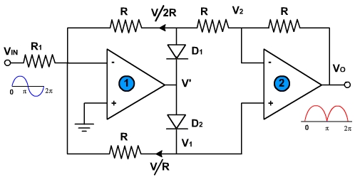
The method of full wave rectification discussed above requires three separate amplifiers. One simpler circuit or active full wave rectifier, which makes use of only two OPAMPs, is shown in fig. 2. It rectifies the input with a gain of R / R1, controllable by one resistor R1.
Fig. 2
When v in is positive then v' = negative, D1 is ON and D2 is virtual ground at the input to (l). Because D2 is non-conducting, and since there is no current in the R which is connected to the non-inverting input to (2), therefore, V1 =0.
Hence, the system consists of two OPAMP in cascade with the gain of A1 equal to (-R / R1) and the gain of A2 equal to (-R / R) = -1.
The resultant at voltage output is
vo = (R / R1 ) vin > 0 (for vin > 0 voltage output of (1) )
Consider now next half cycle when v in is negative. The v' is positive D1 is OFF and D2 is ON. Because of the virtually ground at the input to (2) V2 = V1 = V
Since the input terminals of (2) are at the same (ground) potential, the current coming to the inverting terminal of (1) is as indicated in fig. 2.
The output voltage is vo = i R + v where i = v / 2R (because input impedance of OPAMP is very high).
The sign of vo is again positive because vin is negative in this half cycle. Therefore, outputs during two half cycles are same; and full wave rectified output voltage is obtained also shown in fig. 2.