Voltage shunt Feedback:
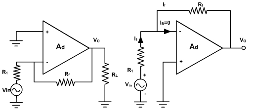
Fig. 1, shows the voltage shunt feedback amplifier using OPAMP.
Fig. 1
The input voltage drives the inverting terminal, and the amplified as well as inverted output signal is also applied to the inverting input via the feedback resistor Rf. This arrangement forms a negative feedback because any increase in the output signal results in a feedback signal into the inverting input signal causing a decrease in the output signal. The non-inverting terminal is grounded. Resistor R1 is connected in series with the source.
The closed loop voltage gain can be obtained by, writing Kirchoff's current equation at the input node V2.
The negative sign in equation indicates that the input and output signals are out of phase by 180. Therefore it is called inverting amplifier. The gain can be selected by selecting Rf and R1 (even < 1).
Inverting Input at Virtual Ground:
In the fig. 1, shown earlier, the noninverting terminal is grounded and the- input signal is applied to the inverting terminal via resistor R1. The difference input voltage vd is ideally zero, (vd= vO/ A) is the voltage at the inverting terminals (v2) is approximately equal to that of the noninverting terminal (v1). In other words, the inverting terminal voltage (v1) is approximately at ground potential. Therefore, it is said to be at virtual ground.