This oscillator can be realized using FET amplifier as shown in fig. 5. The feedback circuit is same as discussed above.
 |
 |
|---|---|
| Fig. 5 | Fig. 6 |
The input impedance of FET is very high so that there is no loading of the feedback circuit. In this circuit, the feedback is voltage series feedback.
Vx =VGS +VS or VGS = Vx - V
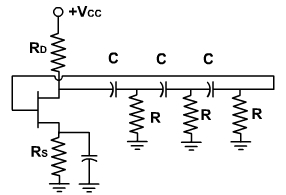
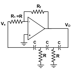
The same circuit can be realizing using OPAMP. The circuit is shown in fig. 6. The input impedance is very high and there is no overloading of feedback circuit. The OPAMP is connected in an inverting configuration and drives three cascaded RC sections. The inverting amplifier causes a 180° phase shift in the signal passing through it. RC network is used in the feedback to provide additional 180° phase shift. Therefore, the total phase shift in the signal, of a particular frequency, around the loop will equal 360° and oscillation will occur at that frequency. The gain necessary to overcome the loss in the RC network and bring the loop gain up to 1 is supplied by the amplifier. The gain is given by
Note that input resistor to the inverting amplifier is also the last resistor of the RC feedback network.
Example -1:
Design a RC phase shift oscillator that will oscillate at 100 Hz.
Solution:
An RC phase shift oscillator using OPAMP is shown in fig. 7. OPAMP is used as an inverting amplifier and provides 180° phase shift. RC network is used in the feedback to provide additional 180° phase shift.
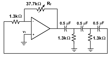
Fig. 7
For an RC phase shift oscillator the frequency is given by
Let C = 0.5 µF. Then
Therefore, Rf= 29 R = 29 (1300Ω) = 37.7 kΩ.
The completed circuit is shown in fig. 7. Rf is made adjustable so the loop gain can be set precisely to 1.
Example - 2
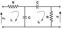
For the network shown in fig. 8 prove that
This network is used with an OPAMP to form an oscillator. Show that the frequency of oscillation is f =1 /2πRC and the gain must exceed 3.
Solution:
To find the frequency of oscillation, let us neglect the loading of the phase shift network. Writing the KV equations,
From equation (E-3),
Fig. 8
Substituting I1 in equation (E-4),.
Solving this equation we get,
Therefore, from equation (E-1),
Putting
, we get,
For phase shift equal to 180° between vf and vo, imaginary term of vf / vo must be zero. Therefore,
This is the frquency of oscillation. Substituting this frequency in vf / vo expression, we get,
This shows that 0° phase shift from vo to vf can be obtained if
and the gain of the feedback circuit becomes 1/3. Therefore, oscillation takes place if the gain of the amplifier exceeds 3.