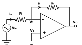
Analog Inverter and Scale Changer:
The circuit of analog inverter is shown in fig. 1. It is same as inverting voltage amplifier.
|
Fig. 1 |
Inverting summer:
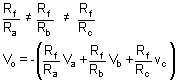
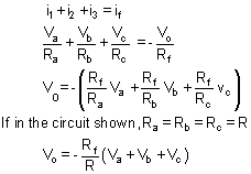
The configuration is shown in fig. 2. With three input voltages va, vb & vc. Depending upon the value of Rf and the input resistors Ra, Rb, Rc the circuit can be used as a summing amplifier, scaling amplifier, or averaging amplifier.
|
Fig. 2 |
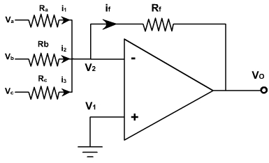
If each input voltage is amplified by a different factor in other words weighted differently at the output, the circuit is called then scaling amplifier.
The circuit can be used as an averaging circuit, in which the output voltage is equal to the average of all the input voltages.
In this case, Ra= Rb= Rc = R and Rf / R = 1 / n where n is the number of inputs. Here Rf / R = 1 / 3.
vo = -(va+ vb + vc) / 3
In all these applications input could be either ac or dc.