No actual current flows until Vin crosses Vtn , as may be seen from Figure 2.11. The operating point of the p -transistor moves from higher to lower values of currents in linear zone. The output voltage is given by ![]() , as may be seen from Figure 2.12.
, as may be seen from Figure 2.12.
Region 2 : the input voltage is in the range ![]() . The upper limit of Vin is Vinv , the logic threshold voltage of the inverter. The logic threshold voltage or the switching point voltage of an inverter denotes the boundary of "logic 1" and "logic 0". It is the output voltage at which Vin = Vout . In this region, the n-transistor moves into saturation, while the p-transistor remains in linear region. The total current through the inverter increases, and the output voltage tends to drop fast.
. The upper limit of Vin is Vinv , the logic threshold voltage of the inverter. The logic threshold voltage or the switching point voltage of an inverter denotes the boundary of "logic 1" and "logic 0". It is the output voltage at which Vin = Vout . In this region, the n-transistor moves into saturation, while the p-transistor remains in linear region. The total current through the inverter increases, and the output voltage tends to drop fast.
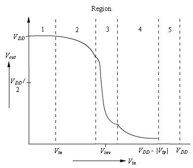
Figure 2.12 Transfer characteristics of the CMOS inverter