The Poynting vector of the radiation field
 .......(7.26)
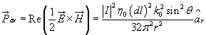
is directed radially outward.
The terms varying as 1/r2 and 1/r3 in (7.23a) and (7.23b) constitutes near zone reactive field for ![]() . These fields do not contribute to the radiated power, rather they represent stored electric and magnectic energy in space in the vicinity of the antenna and account for the reactive part of the impedance seen looking into the antenna terminals. Therefore, in antenna impedance calculation, the near fields are to be taken into account.
. These fields do not contribute to the radiated power, rather they represent stored electric and magnectic energy in space in the vicinity of the antenna and account for the reactive part of the impedance seen looking into the antenna terminals. Therefore, in antenna impedance calculation, the near fields are to be taken into account.
Basic Antenna Parameters:
An antenna does not radiate uniformely in all directions. For the sake of a reference, we consider a hypothetical antenna called an isotropic radiator having equal radiation in all directions. A directional antenna is one which can rediate or receive electromagnetic waves more effectively in some directions than in others. The relative distribution of radiated power as a function of direction in space (i.e., as function of ![]() and
and ![]() ) is called the radiation pattern of the antenna. Instead of 3D surface, it is common practice to show planar cross section radiation pattern. E-plane and H-plane patterns give two most important views. The E-plane pattern is a view obtained from a section containing maximum value of the radiated field and electric field lies in the plane of the section. Similarly when such a section is taken such that the plane of the section contains H field and the direction of maximum radiation.
) is called the radiation pattern of the antenna. Instead of 3D surface, it is common practice to show planar cross section radiation pattern. E-plane and H-plane patterns give two most important views. The E-plane pattern is a view obtained from a section containing maximum value of the radiated field and electric field lies in the plane of the section. Similarly when such a section is taken such that the plane of the section contains H field and the direction of maximum radiation.
A typical radiation pattern plot is shown in fig(7.3).