In this section, the relation between and is discussed. We assume that gate-body voltage drop is more than threshold voltage, so that mobile electrons are created in the channel. This implies that the transistor is either in linear or saturation region.
Here we will derive some simple I-V characteristics of MOSFET, assuming that the device essentially acts as a variable resistor between source and drain, and only drift ohmic current needs to be calculated. Also note that the MOSFET is basically a two-dimensional device. The gate voltageproduces a field in the vertical (x) direction, which induces charge in the silicon, including charge in the inversion layer. The voltage produces a field in the lateral (y) direction, and current flows (predominantly) in the y-direction. Strictly speaking, we must solve the 2-D Poisson and continuity equations to evaluate the I-V characteristics of the device. These are analytically intractable. We therefore resort to the gradual channel approximation described below.
To find the current flowing in the MOS transistor, we need to know the charge in the inversion layer. This charge, Qn(y) (per sq. cm ) is a function of position along the channel, since the potential varies going from source to drain. We assume that Qn(y) can be found at any point y by solving the Poisson equation only in the x direction, that is treating the gate-oxide-silcon system in the channel region very much like a MOS capacitor. This is equivalent to assuming that vertical electric field Ex is much larger than the horizontal electric field Ey, so that the solution of the 1-dimensional Poisson equation is adequate. This gradual channel approximation (the voltage varies only gradually along the channel) is quite valid for long channel MOSFETs since Ey is small. For Qn(y) using charge control relation at location y we have :
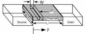
Now we turn our attention to evaluate the resistance of the infinitesimal element of length dy along the channel(as shown in fig 6.21). Assuming that only drift current is present and hence applying Ohm's law, we get :
Here we havel = dy, and A=Wxi, where xi=inversion layer thickness.
Now using equation (6.22), We have :
Fig 6.21: Cross Sectional View of channel
Since is varying along the transverse direction, we define as :