Measurement of Unknown Impedance(Practical Consideration)
While practically implementing the above scheme one would also notice that invariably the location of unknown impedance is not precisely defined. As a result the measurement of may have some error which in turn will result into an error in the load impedance.
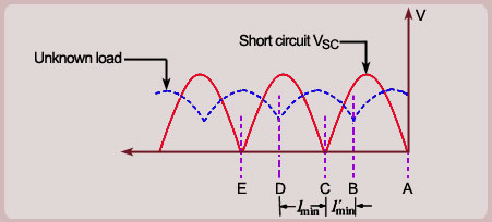
To overcome this problem the measurement is carried out in two steps. First, the standing wave pattern is obtained with the unknown load as explained above. Now replace the unknown impedance by an ideal short-circuit and obtain
the standing wave pattern again. The two standing wave patterns are shown as below
At the short circuit point (which is also the location of the unknown impedance) the voltage is zero. The voltage is
also zero at points which are multiple of away from it. i.e., at point C, E etc. The points C, E etc represent
impedance conditions identical to that at A, that is, the impedance at C or E is equal to the unknown impedance.
The unknown impedance therefore can be obtained by transforming impedance at B or D to point C. If impedance
is transformed from D to C the distance is negative, whereas if the transformation is made from B to C the
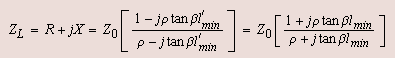
distance is positive. The unknown impedance therefore can be evaluated as
One can note here that . In the impedance calculation either of or can be used. As long
as the sign of the distance is taken correctly it does not matter which of the minima is taken for impedance transformation.