

Contents
System Specifications
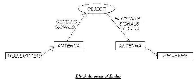
The objective of radar is to transmit radio frequency energy toward a
target and to receive and process the reflected energy. Radar equipment
can be divided into three basic component groups: the transmitter, the
receiver, and the antenna.
Theory & Working:
Radar operates on the principle that objects in the path of radio waves reflect or reradiate some portion of the wave, enabling those objects to be detected and tracked at long-range distances. Radar is an instrument that basically includes transmitter, antenna, and receiver. Besides them there are timer, modulator and display unit. The complexity of the transmitter and receiver depends upon the modulation format and the signal processing methods to be used and the complexity of antenna depends upon the radar frequency and operational expectations. Usually, radars are monostatic and duplexer is used to switch it between transmission and reception. The basic parts of radar are shown below.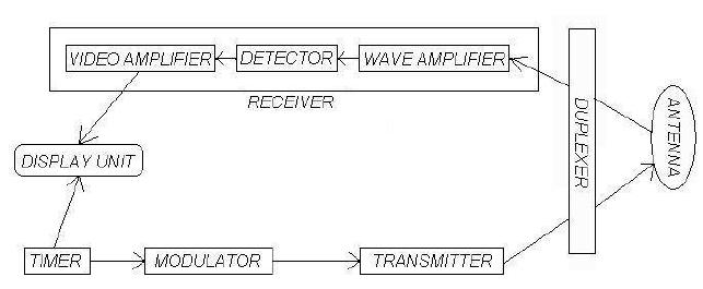
1) Timer: It is also known as the synchronizer. The timer generates the trigger pulses at a specific frequency. Each pulse turns on the modulator. The timer has two outputs, one to the modulator and other to the display unit. The main function of the timer is to produce trigger pulses that start the transmitter and display unit.
2) Modulator: The modulator is turned on by the pulses produced by the timer. It in turn produces another pulse of the required shape and duration with sufficient power and passes it to the transmitter. The modulator also maintains the intervals between pulses. The peak power of the transmitted radio signal pulse depends on the amplitude of the modulator pulse.
3) Transmitter: The transmitter is turned on by the pulses produced by the modulator. It is basically a simple oscillator that produces a radio wave output for the duration of the pulse provided by the modulator and sends it to the duplexer.
4) Duplexer: The antenna is shared for the transmission of energy and the receiving of the returned energy. It is a fast-acting electronic switch that permits the single antenna to be shared for both the transmission and reception. It is responsible for channeling the transmitted power to the antenna and the returned energy to the receiver.
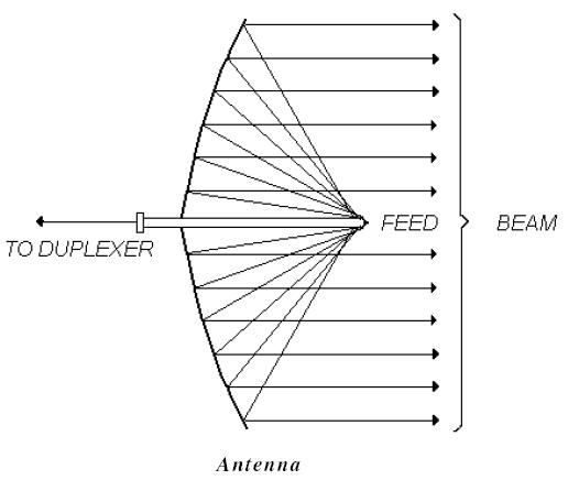
5) Antenna: The antenna is connected to the duplexer. The transmitter power is radiated into space by a highly directional, high-gain antenna that concentrates the energy into a narrow beam. Most antennas used in radar applications have parabolic reflector. The antenna radiates the radio waves into the reflector. The reflector reflects the waves in the form of a narrow beam that is parallel to the feed. See figure. The narrow, directive beam not only concentrates the energy on target but also measures the direction to the target. On reception, the antenna collects the energy contained in the returned signal and delivers it to the duplexer. The shape and size of the antenna depends upon its use and the radio signals it radiates and receives. The design of the antenna determines its directivity and gain.
6) Receiver: The function of the receiver is to detect desired signals in the presence of noise and interference. The receiver processes the returned energy and sends the signal to a display unit. Target detection is done within the receiver. The received signal passes through a wave amplifier where it is amplified and then passed on to the detector. The detector converts it to DC and filters the signal resulting in a signal in video form. The signal pulse then passes to the video amplifier where its strength is increased and the signal is cleaned up. The signal pulse is then displayed.
Meteorologists recognized the applicability of radar in meteorological studies and based their initial work on radar pattern recognition. The most conceptually simple method is that of contouring. A description of contours of a digitally defined echo area may be derived from a Fourier series expansion. Fourier expansion approximates a digital contour and it can be seen that as few as five harmonics may be used to provide quite a detailed description of an echo if only one intensity level is used.
Radar data is usually used for short range forecasting. The meteorological predictions are made by tracking echo areas from one radar picture to the next. This is done by echo matching or echo correlation. The simplest matching procedure is to cross correlate the centroids of each echo (radar picture) with those of the subsequent ones. However cross-correlation techniques may also be used to match portions of one radar picture with portions of subsequent pictures for more accurate results. If there is no significant change from one echo to another the entire picture can be matched. Once the echo movement is defined, then short-period forecasts can be made.

