To sputter insulators as well as conducting materials another technique, so-called radio-frequency (RF) sputtering, as depicted in Figure 39.3, is used. Usually a large capacitor (500-2000 pF) is placed in series between the RF power supply and the powered electrode. The large series capacitor allows a significant negative bias to develop on the cathode (self-bias), typically half of the value of the applied peak-to-peak RF voltage (see Figure 39.4). This bias is then the acceleration voltage for ions from the plasma, which move much too slowly to respond to the applied RF potentials.
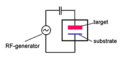
Figure 39.3: Schematic of RF sputtering chamber.
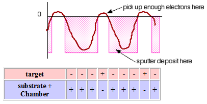
Figure 39.4: Variation of RF bias with time and the responses of target and substrate with RF bias.
The use of a RF generator is essential to maintain the discharge and to avoid charge build-up during the sputtering of insulating materials. Because the positive charges don't need to flow through the target the sputtering of non-conducting materials is also possible. The electrons and ions show different types of responses with the RF frequency: (i) For frequencies less than about 50 kHz: (a) Electrons and ions in plasma are mobile (both follow the switching of the anode and cathode), (b) Basically DC sputtering of both surfaces, (ii) For frequencies above 50 kHz: (a) Ions (heavy) can no longer follow the switching, (b) Electrons can neutralize positive charge build up and the electrons oscillating in the glow region acquire