Figures 26.2 (a) and (b) show the voltage responses for elements 3 and 6 which form symmetric pair. It is clear from Configuration 2 that this pair is situated away from the centre and is subjected to lower stresses in comparison to the other elements. Accordingly, very little change in voltage response is predicted for the above pair.
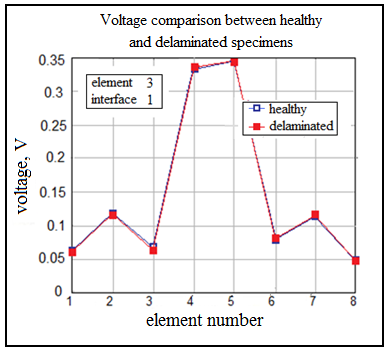
Figure 26.2 (a) Voltage profile for damage in element 3 of interface 1
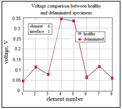
Figure 26.2 (b) Voltage profile for damage in element 6 of interface 1
|