Voltage responses in piezoelectric patches for Configuration 2 are presented for two different interfaces. Figure 26.1 shows the voltage response of the healthy laminate.
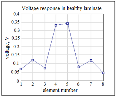
Figure 26.1: Voltage profile in the healthy laminate for Configuration 2
Figures 26.2 (a) to (d) show representative voltage responses obtained in various elements subjected to delamination in interface 1 while Figures 26.3 (a) to (d) for delamination in interface 3. Configuration 2 has a diagonal symmetry of the elements. The elements placed symmetrically with respect to the diagonal dividing the plate in two equal parts show similar voltage responses.
Elements 4 and 5 are subjected to greater stresses due to their location (closer to the centre of the plate) and the voltage response of healthy laminate for these elements is in the range of 0.33V to 0.35V. Other elements are stressed to a lesser extent and have a lower voltage response predicted for them in the range of 0.06V to 0.12V. |