Developing actuator and sensor influence matrices.
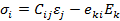
The linear constitutive equations of a piezoelectric layer for the converse and direct piezoelectric effects can be written as
 |
|
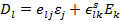 |
(20.1) |
Where and and  are the stress and strain vector, Ek is the electric field vector, Dl is the electric displacement vector, are the stress and strain vector, Ek is the electric field vector, Dl is the electric displacement vector,  is the elastic stiffness matrix, is the elastic stiffness matrix,  is the piezoelectric stress charge tensor and is the piezoelectric stress charge tensor and  is the piezoelectric permittivity matrix. The electric field vector of the piezoelectric layer is related to the electric potential vector V by is the piezoelectric permittivity matrix. The electric field vector of the piezoelectric layer is related to the electric potential vector V by
 |
(20.2) |
The governing equation of motion neglecting material damping for this case can be written as
 |
(20.3) |
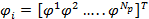
 and and  are the structural nodal acceleration and displacement vectors. are the structural nodal acceleration and displacement vectors.  ] and ] and  are the structural mass and stiffness matrices. F is the global force vector; are the structural mass and stiffness matrices. F is the global force vector;  is the structural electro-mechanical matrix and is the structural electro-mechanical matrix and  is the actuator voltage vector. The equivalent forces is the actuator voltage vector. The equivalent forces  dadue to the actuator voltages can be expressed as. dadue to the actuator voltages can be expressed as.  . The controller is designed after the placement of actuators and sensors. Therefore, the mass, damping and the stiffness matrices will not contain feedback gain elements explicitly; although change in location of actuators across the layers will change all these matrices. The analysis is done for collocated sensor and actuator. The electric voltage vector of the element can be expressed as . The controller is designed after the placement of actuators and sensors. Therefore, the mass, damping and the stiffness matrices will not contain feedback gain elements explicitly; although change in location of actuators across the layers will change all these matrices. The analysis is done for collocated sensor and actuator. The electric voltage vector of the element can be expressed as
 |
(20.4) |
Np is the number of piezoelectric layers and  is the electric voltage of the kth piezoelectric layer in the i th element. is the electric voltage of the kth piezoelectric layer in the i th element.
|