|
Venturimeter
Construction: A venturimeter
is essentially a short pipe (Fig. 15.1) consisting of two
conical parts with a short portion of uniform cross-section
in between. This short portion has the minimum area and is
known as the throat. The two conical portions have the same
base diameter, but one is having a shorter length with a larger
cone angle while the other is having a larger length with
a smaller cone angle.
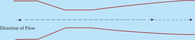
Fig 15.1 A
Venturimeter
Working:
- The venturimeter is always used in a
way that the upstream part of the flow takes place through
the short conical portion while the downstream part of the
flow through the long one.
- This ensures a rapid converging passage
and a gradual diverging passage in the direction of flow
to avoid the loss of energy due to separation. In course
of a flow through the converging part, the velocity increases
in the direction of flow according to the principle of continuity,
while the pressure decreases according to Bernoulli’s
theorem.
- The velocity reaches its maximum value
and pressure reaches its minimum value at the throat. Subsequently,
a decrease in the velocity and an increase in the pressure
takes place in course of flow through the divergent part.
This typical variation of fluid velocity and pressure by
allowing it to flow through such a constricted convergent-divergent
passage was first demonstrated by an Italian scientist Giovanni
Battista Venturi in 1797.
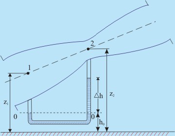
Fig 15.2 Measurement
of Flow by a Venturimeter
- Figure 15.2 shows that a venturimeter
is inserted in an inclined pipe line in a vertical plane
to measure the flow rate through the pipe. Let us consider
a steady, ideal and one dimensional (along the axis of the
venturi meter) flow of fluid. Under this situation, the
velocity and pressure at any section will be uniform.
- Let the velocity and pressure at the
inlet (Sec. 1) are V1 and p1 respectively,
while those at the throat (Sec. 2) are V2 and
p2. Now, applying Bernoulli’s equation
between Secs 1 and 2, we get
|
(15.1) |
 |
(15.2) |
where ρ is the density
of fluid flowing through the venturimeter.
 |
(15.3) |
where A1 and A2
are the cross-sectional areas of the venturi meter at its
throat and inlet respectively.
- With the help of Eq. (15.3), Eq.
(15.2) can be written as

|
|
 |
(15.4) |
|