Francis Turbine
Reaction Turbine: The principal feature of a reaction turbine that distinguishes it from an impulse turbine is that only a part of the total head available at the inlet to the turbine is converted to velocity head, before the runner is reached. Also in the reaction turbines the working fluid, instead of engaging only one or two blades, completely fills the passages in the runner. The pressure or static head of the fluid changes gradually as it passes through the runner along with the change in its kinetic energy based on absolute velocity due to the impulse action between the fluid and the runner. Therefore the cross-sectional area of flow through the passages of the fluid. A reaction turbine is usually well suited for low heads. A radial flow hydraulic turbine of reaction type was first developed by an American Engineer, James B. Francis (1815-92) and is named after him as the Francis turbine. The schematic diagram of a Francis turbine is shown in Fig. 28.1
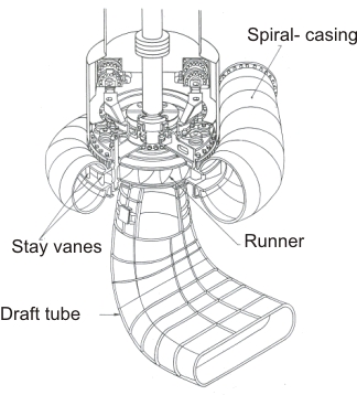 |
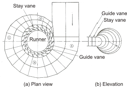
Figure 28.1 A Francis turbine |
A Francis turbine comprises mainly the four components:
(i) sprical casing,
(ii) guide on stay vanes,
(iii) runner blades,
(iv) draft-tube as shown in Figure 28.1 .
Spiral Casing : Most of these machines have vertical shafts although some smaller machines of this type have horizontal shaft. The fluid enters from the penstock (pipeline leading to the turbine from the reservoir at high altitude) to a spiral casing which completely surrounds the runner. This casing is known as scroll casing or volute. The cross-sectional area of this casing decreases uniformly along the circumference to keep the fluid velocity constant in magnitude along its path towards the guide vane.
Figure 28.2 Spiral Casing |
This is so because the rate of flow along the fluid path in the volute decreases due to continuous entry of the fluid to the runner through the openings of the guide vanes or stay vanes.
Guide or Stay vane:
The basic purpose of the guide vanes or stay vanes is to convert a part of pressure energy of the fluid at its entrance to the kinetic energy and then to direct the fluid on to the runner blades at the angle appropriate to the design. Moreover, the guide vanes are pivoted and can be turned by a suitable governing mechanism to regulate the flow while the load changes. The guide vanes are also known as wicket gates. The guide vanes impart a tangential velocity and hence an angular momentum to the water before its entry to the runner. The flow in the runner of a Francis turbine is not purely radial but a combination of radial and tangential. The flow is inward, i.e. from the periphery towards the centre. The height of the runner depends upon the specific speed. The height increases with the increase in the specific speed. The main direction of flow change as water passes through the runner and is finally turned into the axial direction while entering the draft tube.
Draft tube:
The draft tube is a conduit which connects the runner exit to the tail race where the water is being finally discharged from the turbine. The primary function of the draft tube is to reduce the velocity of the discharged water to minimize the loss of kinetic energy at the outlet. This permits the turbine to be set above the tail water without any appreciable drop of available head. A clear understanding of the function of the draft tube in any reaction turbine, in fact, is very important for the purpose of its design. The purpose of providing a draft tube will be better understood if we carefully study the net available head across a reaction turbine.
Net head across a reaction turbine and the purpose to providing a draft tube . The effective head across any turbine is the difference between the head at inlet to the machine and the head at outlet from it. A reaction turbine always runs completely filled with the working fluid. The tube that connects the end of the runner to the tail race is known as a draft tube and should completely to filled with the working fluid flowing through it. The kinetic energy of the fluid finally discharged into the tail race is wasted. A draft tube is made divergent so as to reduce the velocity at outlet to a minimum. Therefore a draft tube is basically a diffuser and should be designed properly with the angle between the walls of the tube to be limited to about 8 degree so as to prevent the flow separation from the wall and to reduce accordingly the loss of energy in the tube. Figure 28.3 shows a flow diagram from the reservoir via a reaction turbine to the tail race.
The total head  at the entrance to the turbine can be found out by applying the Bernoulli's equation between the free surface of the reservoir and the inlet to the turbine as at the entrance to the turbine can be found out by applying the Bernoulli's equation between the free surface of the reservoir and the inlet to the turbine as
 |
(28.1) |
where  is the head lost due to friction in the pipeline connecting the reservoir and the turbine. Since the draft tube is a part of the turbine, the net head across the turbine, for the conversion of mechanical work, is the difference of total head at inlet to the machine and the total head at discharge from the draft tube at tail race and is shown as H in Figure 28.3 is the head lost due to friction in the pipeline connecting the reservoir and the turbine. Since the draft tube is a part of the turbine, the net head across the turbine, for the conversion of mechanical work, is the difference of total head at inlet to the machine and the total head at discharge from the draft tube at tail race and is shown as H in Figure 28.3
Figure 28.3 Head across a reaction turbine |
Therefore, H = total head at inlet to machine (1) - total head at discharge (3)
 |
(28.3) |
 |
(28.4) |
The pressures are defined in terms of their values above the atmospheric pressure. Section 2 and 3 in Figure 28.3 represent the exits from the runner and the draft tube respectively. If the losses in the draft tube are neglected, then the total head at 2 becomes equal to that at 3. Therefore, the net head across the machine is either  or or  . Applying the Bernoull's equation between 2 and 3 in consideration of flow, without losses, through the draft tube, we can write. . Applying the Bernoull's equation between 2 and 3 in consideration of flow, without losses, through the draft tube, we can write.
 |
(28.5) |
 |
(28.6) |
Since  , both the terms in the bracket are positive and hence , both the terms in the bracket are positive and hence  is always negative, which implies that the static pressure at the outlet of the runner is always below the atmospheric pressure. Equation (28.1) also shows that the value of the suction pressure at runner outlet depends on z, the height of the runner above the tail race and is always negative, which implies that the static pressure at the outlet of the runner is always below the atmospheric pressure. Equation (28.1) also shows that the value of the suction pressure at runner outlet depends on z, the height of the runner above the tail race and  , the decrease in kinetic energy of the fluid in the draft tube. The value of this minimum pressure , the decrease in kinetic energy of the fluid in the draft tube. The value of this minimum pressure  should never fall below the vapour pressure of the liquid at its operating temperature to avoid the problem of cavitation. Therefore, we fine that the incorporation of a draft tube allows the turbine runner to be set above the tail race without any drop of available head by maintaining a vacuum pressure at the outlet of the runner. should never fall below the vapour pressure of the liquid at its operating temperature to avoid the problem of cavitation. Therefore, we fine that the incorporation of a draft tube allows the turbine runner to be set above the tail race without any drop of available head by maintaining a vacuum pressure at the outlet of the runner. |