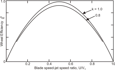
The condition given by Eq. (26.5) states that the efficiency of the wheel in converting the kinetic energy of the jet into mechanical energy of rotation becomes maximum when the wheel speed at the centre of the bucket becomes one half of the incoming velocity of the jet. The overall efficiency will be less than because of friction in bearing and windage, i.e. friction between the wheel and the atmosphere in which it rotates. Moreover, as the losses due to bearing friction and windage increase rapidly with speed, the overall efficiency reaches it peak when the ratio is slightly less than the theoretical value of 0.5. The value usually obtained in practice is about 0.46. The Figure 27.1 shows the variation of wheel efficiency with blade to jet speed ratio for assumed values at k=1 and 0.8, and
. An overall efficiency of 85-90 percent may usually be obtained in large machines. To obtain high values of wheel efficiency, the buckets should have smooth surface and be properly designed. The length, width, and depth of the buckets are chosen about 2.5.4 and 0.8 times the jet diameter. The buckets are notched for smooth entry of the jet.
Figure 27.1 Theoretical variation of wheel efficiency for a Pelton turbine with blade speed to jet speed ratio for different values of k
Specific speed and wheel geometry . The specific speed of a pelton wheel depends on the ratio of jet diameter d and the wheel pitch diameter. D (the diameter at the centre of the bucket). If the hydraulic efficiency of a pelton wheel is defined as the ratio of the power delivered P to the wheel to the head available H at the nozzle entrance, then we can write.
 will be less than
  because of friction in bearing and windage, i.e. friction between the wheel and the atmosphere in which it rotates. Moreover, as the losses due to bearing friction and windage increase rapidly with speed, the overall efficiency reaches it peak when the ratio
  is slightly less than the theoretical value of 0.5. The value usually obtained in practice is about 0.46. The Figure 27.1 shows the variation of wheel efficiency
  . An overall efficiency of 85-90 percent may usually be obtained in large machines. To obtain high values of wheel efficiency, the buckets should have smooth surface and be properly designed. The length, width, and depth of the buckets are chosen about 2.5.4 and 0.8 times the jet diameter. The buckets are notched for smooth entry of the jet.