IMPULSE TURBINE
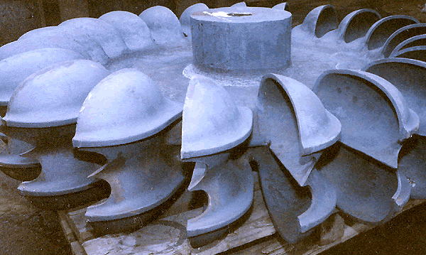
Figure 26.1 Typical PELTON WHEEL with 21 Buckets |
Hydropower is the longest established source for the generation of electric power. In this module we shall discuss the governing principles of various types of hydraulic turbines used in hydro-electric power stations.
Impulse Hydraulic Turbine : The Pelton Wheel
The only hydraulic turbine of the impulse type in common use, is named after an American engineer Laster A Pelton, who contributed much to its development around the year 1880. Therefore this machine is known as Pelton turbine or Pelton wheel. It is an efficient machine particularly suited to high heads. The rotor consists of a large circular disc or wheel on which a number (seldom less than 15) of spoon shaped buckets are spaced uniformly round is periphery as shown in Figure 26.1. The wheel is driven by jets of water being discharged at atmospheric pressure from pressure nozzles. The nozzles are mounted so that each directs a jet along a tangent to the circle through the centres of the buckets (Figure 26.2). Down the centre of each bucket, there is a splitter ridge which divides the jet into two equal streams which flow round the smooth inner surface of the bucket and leaves the bucket with a relative velocity almost opposite in direction to the original jet.
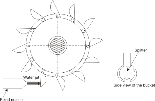 |
Figure 26.2 A Pelton wheel |
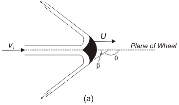
For maximum change in momentum of the fluid and hence for the maximum driving force on the wheel, the deflection of the water jet should be  . In practice, however, the deflection is limited to about . In practice, however, the deflection is limited to about  so that the water leaving a bucket may not hit the back of the following bucket. Therefore, the camber angle of the buckets is made as so that the water leaving a bucket may not hit the back of the following bucket. Therefore, the camber angle of the buckets is made as   . Figure(26.3a) . Figure(26.3a)
The number of jets is not more than two for horizontal shaft turbines and is limited to six for vertical shaft turbines. The flow partly fills the buckets and the fluid remains in contact with the atmosphere. Therefore, once the jet is produced by the nozzle, the static pressure of the fluid remains atmospheric throughout the machine. Because of the symmetry of the buckets, the side thrusts produced by the fluid in each half should balance each other.
Analysis of force on the bucket and power generation Figure 26.3a shows a section through a bucket which is being acted on by a jet. The plane of section is parallel to the axis of the wheel and contains the axis of the jet. The absolute velocity of the jet  with which it strikes the bucket is given by with which it strikes the bucket is given by
| Figure 26.3 |
(a)Flow along the bucket of a pelton wheel |
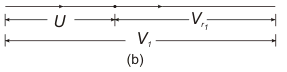
| (b) Inlet velocity triangle |
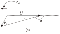
| (c)Outlet velocity triangle |
where,  is the coefficient of velocity which takes care of the friction in the nozzle. H is the head at the entrance to the nozzle which is equal to the total or gross head of water stored at high altitudes minus the head lost due to friction in the long pipeline leading to the nozzle. Let the velocity of the bucket (due to the rotation of the wheel) at its centre where the jet strikes be U . Since the jet velocity is the coefficient of velocity which takes care of the friction in the nozzle. H is the head at the entrance to the nozzle which is equal to the total or gross head of water stored at high altitudes minus the head lost due to friction in the long pipeline leading to the nozzle. Let the velocity of the bucket (due to the rotation of the wheel) at its centre where the jet strikes be U . Since the jet velocity  is tangential, i.e. is tangential, i.e.  and U are collinear, the diagram of velocity vector at inlet (Fig 26.3.b) becomes simply a straight line and the relative velocity is given by and U are collinear, the diagram of velocity vector at inlet (Fig 26.3.b) becomes simply a straight line and the relative velocity is given by
 |
It is assumed that the flow of fluid is uniform and it glides the blade all along including the entrance and exit sections to avoid the unnecessary losses due to shock. Therefore the direction of relative velocity at entrance and exit should match the inlet and outlet angles of the buckets respectively. The velocity triangle at the outlet is shown in Figure 26.3c. The bucket velocity U remains the same both at the inlet and outlet. With the direction of U being taken as positive, we can write. The tangential component of inlet velocity (Figure 26.3b)
and the tangential component of outlet velocity (Figure 26.3c)
|