GAS TURBINE
Again applying the angular momentum relation-ship, we may show that the power output as,
 |
(13.1) |
In an axial turbine,
The work output per unit mass flow rate is
We find that the stage work ratio is
 |
(13.2) |
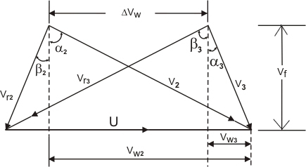
Figure 13.2 illustrates a combined (inlet to and exit from the rotor ) velocity diagram of a turbine stage.
Figure 13.2 Combined velocity diagram |
The velocity diagram gives the following relation:
The Eq (13.3) gives the expression for  in terms of gas angles associated with the rotor blade. in terms of gas angles associated with the rotor blade.
Note that the "work-done factor" required in the case of the axial compressor is unnecessary here. This is because in an accelerating flow the effect of the growth of boundary layer along the annulus passage in much less than when there is a decelerating flow with an adverge pressure gradient.
Instead of temperature drop ratio [defined in Eq (13.2)], turbine designers generally refer to the work capacity of a turbine stage as,
 is a dimensionless parameter, which is called the "blade loading capacity" or "temperature drop coefficient". In gas turbine design, is a dimensionless parameter, which is called the "blade loading capacity" or "temperature drop coefficient". In gas turbine design,  is kept generally constant across a stage and the ratio is kept generally constant across a stage and the ratio
 is called "the flow coefficient" is called "the flow coefficient"  . .
Thus, Eq (13.4) can be written as,
 |
(13.5) |
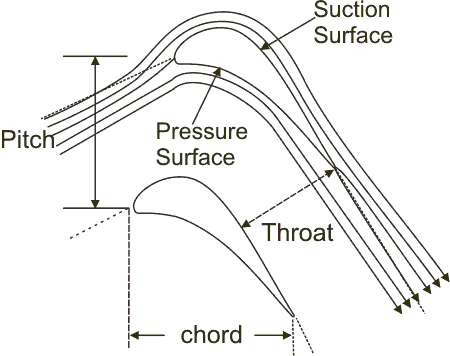
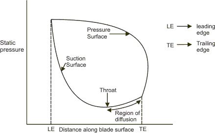
As the boundary layer over the blade surface is not very sensitive in the case of a turbine, the turbine designer has considerably more freedom to distribute the total stage pressure drop between the rotor and the stator. However, locally on the suction surface of the blade there could be a zone of an adverse pressure gradient depending on the turning and on the pitch of the blades. Thus, the boundary layer could grow rapidly or even separate in such a region affecting adversely the turbine efficiency. Figure 13.3 illustrates the schematic of flow within the blade passage and the pressure distribution over the section surface depicting a zone of diffusion. Different design groups have their own rules, learned from experience of blade testing, for the amount of diffusion which is permissible particularly for highly loaded blades.
| Figure 13.3a Schematic diagram of flow through a turbine blade passage |
Figure13.3b Pressure distribution around a turbine blade |
|