GAS TURBINE
Two-dimensional theory of axial flow turbine.
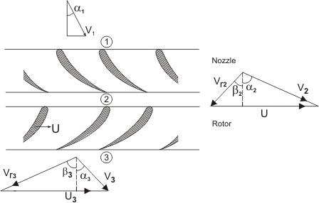
An axial turbine stage consists of a row of stationary blades, called nozzles or stators, followed by the rotor, as Figure 13.1 illustrates. Because of the large pressure drop per stage, the nozzle and rotor blades may be of increasing length, as shown, to accommodate the rapidly expanding gases, while holding the axial velocity to something like a uniform value through the stage.
It should be noted that the hub-tip ratio for a high pressure gas turbine in quite high, that is, it is having blades of short lengths. Thus, the radial variation in velocity and pressure may be neglected and the performance of a turbine stage is calculated from the performance of the blading at the mean radial section, which is a two-dimensional "pitch-line design analysis ". A low-pressure turbine will typically have a much lower hub-tip ratio and a larger blade twist. A two dimensional design is not valid in this case.
In two dimensional approach the flow velocity will have two components, one axial and the other peripheral, denoted by subscripts 'f' and  respectively. The absolute velocity is denoted by V and the relative velocity with respect to the impeller by respectively. The absolute velocity is denoted by V and the relative velocity with respect to the impeller by  . The flow conditions '1' indicates inlet to the nozzle or stator vane, '2' exit from the nozzle or inlet to the rotor and '3' exit form the rotor. Absolute angle is represented by . The flow conditions '1' indicates inlet to the nozzle or stator vane, '2' exit from the nozzle or inlet to the rotor and '3' exit form the rotor. Absolute angle is represented by  and relative angle by and relative angle by  as before. as before.
Figure 13.1 Axial Turbine Stage |
A section through the mean radius would appear as in Figure.13.1. One can see that the nozzles accelerate the flow imparting an increased tangential velocity component. The velocity diagram of the turbine differs from that of the compressor in that the change in tangential velocity in the rotor,
 , is in the direction opposite to the blade speed U. The reaction to this change in the tangential momentum of the fluid is a torque on the rotor in the direction of motion. Hence the fluid does work on the rotor. , is in the direction opposite to the blade speed U. The reaction to this change in the tangential momentum of the fluid is a torque on the rotor in the direction of motion. Hence the fluid does work on the rotor.
|