Elementary Cascade Theory
The previous module dealt with the axial flow compressors, where all the analyses were based on the flow conditions at inlet to and exit from the impeller following kinematics of flow expressed in terms of velocity triangles. However, nothing has been mentioned about layout and design of blades, which are aerofoil sections.
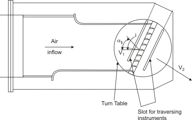
In the development of the highly efficient modern axial flow compressor or turbine, the study of the two-dimensional flow through a cascade of aerofoils has played an important part. An array of blades representing the blade ring of an actual turbo machinery is called the cascade. Figure 11.1a shows a compressor blade cascade tunnel. As the air stream is passed through the cascade, the direction of air is turned. Pressure and velocity measurements are made at up and downstream of cascade as shown. The cascade is mounted on a turn-table so that its angular direction relative to the direction of inflow can be changed, which enables tests to be made for a range of incidence angle. As the flow passes through the cascade, it is deflected and there will be a circulation  and thus the lift generated will be and thus the lift generated will be  (Fig 11.1b & 11.1c). (Fig 11.1b & 11.1c).
 is the mean velocity that makes an angle is the mean velocity that makes an angle
 with the axial direction. with the axial direction.
Figure 11.1a A Cascade Tunnel |
Compressor cascade :
For a compressor cascade, the static pressure will rise across the cascade, i.e. 
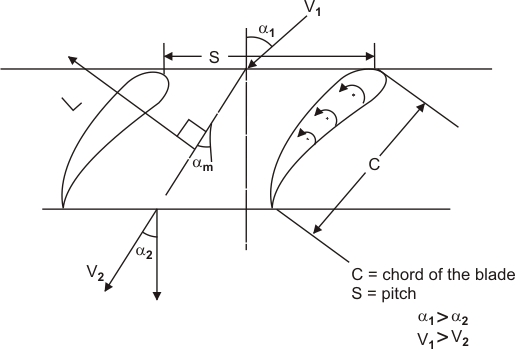
Figure 11.1b Compressor Cascade |
C =chord of the blade
S = pitch


|
 |
Figure 11.1c Velocity triangle |
Circulation: 
Lift =  Lift coefficient, 

from velocity triangles,


 where where 
|