Compressors
In Module 1, we discussed the basic fluid mechanical principles governing the energy transfer in a fluid machine. A brief description of different types of fluid machines using water as the working fluid was also given in Module 1.However, there exist a large number of fluid machines in practice, that use air, steam and gas (the mixture of air and products of burnt fuel) as the working fluids. The density of the fluids change with a change in pressure as well as in temperature as they pass through the machines. These machines are called 'compressible flow machines' and more popularly 'turbomachines'. Apart from the change in density with pressure, other features of compressible flow, depending upon the regimes, are also observed in course of flow of fluids through turbomachines. Therefore, the basic equation of energy transfer (Euler's equation, as discussed before) along with the equation of state relating the pressure, density and temperature of the working fluid and other necessary equations of compressible flow, are needed to describe the performance of a turbomachine. However, a detailed discussion on all types of turbomachines is beyond the scope of this book. We shall present a very brief description of a few compressible flow machines, namely, compressors, fans and blowers in this module. In practice two kinds of compressors:centrifugal and axial are generally in use.
Centrifugal Compressors
A centrifugal compressor is a radial flow rotodynamic fluid machine that uses mostly air as the working fluid and utilizes the mechanical energy imparted to the machine from outside to increase the total internal energy of the fluid mainly in the form of increased static pressure head.
During the second world war most of the gas turbine units used centrifugal compressors. Attention was focused on the simple turbojet units where low power-plant weight was of great importance. Since the war, however, the axial compressors have been developed to the point where it has an appreciably higher isentropic efficiency. Though centrifugal compressors are not that popular today, there is renewed interest in the centrifugal stage, used in conjunction with one or more axial stages, for small turbofan and turboprop aircraft engines.
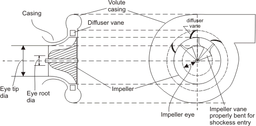
A centrifugal compressor essentially consists of three components.
- A stationary casing
- A rotating impeller as shown in Fig. 6.1 (a) which imparts a high velocity to the air. The impeller may be single or double sided as show in Fig. 6.1 (b) and (c), but the fundamental theory is same for both.
- A diffuser consisting of a number of fixed diverging passages in which the air is decelerated with a consequent rise in static pressure.
Figure 6.1 Schematic views of a centrifugal compressor |
Figure 6.2 Single entry and single outlet centrifugal compresssor |
Figure 6.2 is the schematic of a centrifugal compressor, where a single entry radial impeller is housed inside a volute casing. |