Imaging Rayleigh-Benard convection
The apparatus used for the study of Rayleigh-Benard convection is shown schematically in Figure 2.
The test cell consists of three sections namely the top tank, the middle test section and the bottom tank.
The cavity is 447 mm in length with a square cross-section  , the dimensional tolerance
being , the dimensional tolerance
being  . The top and bottom surfaces of the cavity are made of aluminum, 3 mm thick. The side
walls of the cavity are made of Plexiglas, 10 mm thickness and bakelite sheet of thickness 15 mm to
provide thermally insulating side wall conditions. Optical windows (Standa, BK-7 glass, . The top and bottom surfaces of the cavity are made of aluminum, 3 mm thick. The side
walls of the cavity are made of Plexiglas, 10 mm thickness and bakelite sheet of thickness 15 mm to
provide thermally insulating side wall conditions. Optical windows (Standa, BK-7 glass,  ) are used to
confine the fluid inside the test cavity and the passage of light is arranged in the direction normal to their
planes and parallel to the side walls. Temperature differences between the top and bottom wall of the
cavity are set equal to 10 K and 15 K. ) are used to
confine the fluid inside the test cavity and the passage of light is arranged in the direction normal to their
planes and parallel to the side walls. Temperature differences between the top and bottom wall of the
cavity are set equal to 10 K and 15 K.
For maintaining uniform cold temperature over the top surface, a tank carrying cold fluid is fixed
above it (Figure 2). Special arrangements ensure that the lower surface of the tank and the top surface of
the cold wall are in good thermal contact. For the lower heated surface, an aluminum tank with baffles is
fabricated and assembled with the test cavity. These baffles introduce a tortuous path to the flow of hot
water and increase the effective interfacial contact area. For maintaining uniform and constant
temperatures at the upper and lower surfaces of the cavity, a large volume of water is circulated from
constant temperature baths (Huber-variostat and Raaga-cryostat). Temperature measurements at the
heated and cooled surfaces are carried out using thermocouples that are connected to a 32-channel
temperature recorder (Sanei, hybrid recorder).
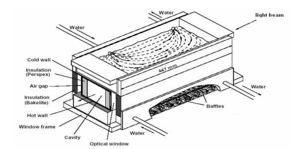
Figure 2: Test cell for imaging Rayleigh-Benard convestion in a rectangular cavity.
|