Shadowgraph
The shadowgraph arrangement depends on the change in the light intensity arising from beam displacement from its original path. When passing through the test field under investigation, the individual light rays are refracted and bent out of their original path. The rays traversing the region that has no gradient are not deflected, whereas the rays traversing the region that has non zero gradients are bent up. Figure 5.7 illustrates the shadowgraph effect using simple geometric ray tracing. Here a plane wave traverses a medium that has a nonuniform index of refraction distribution and is allowed to illuminate a screen. The resulting image on the screen consists of regions where the rays converege and diverge; these appear as light and dark regions respectively. It is this effect that gives the technique its name because gradients leave a shadow, or dark region, on the viewing screen. A particular deflected light ray that arrives at a point different from the original point of the recording plane should be traced. It leads to a distribution of light intensity in that plane altered with respect to the undistributed case.
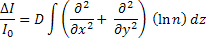
When subjected to linear approximations that includes small displacement of the light ray, a second order partial differential equation can be derived for the refractive index feild with respect to intensity contrast in the shadowgraph image. Let D be the distance of the screen from the optical window on the beaker. The governing equation for a shadowgraph process can be expressed as
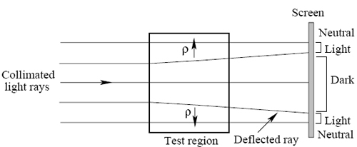
Figure 5.7: Illustration of the shadowgraph arrangement
|