| |
Experimental Details
The apparatus used to steady convection in the horizontal layer of air is shown in Figure 4.46. The cavity employed was  in plan, the vertical depth being adjustable. Two different vertical depths were used in the present study to generate the two Rayleigh numbers. For the higher Rayleigh number of 1.39x10⁴, the vertical depth was 20mm. for the higher Rayleigh number 1.39x10⁴, the vertical depth was 20mm. for the higher Rayleigh number of 4.02 x 10⁴, the vertical depth was increased to 26.8mm. The aspect ratio was thus maintained at 25 and 18.6 respectively. The lowering of the aspect ratio was seen to reduce the extent of unsteadiness in the convection pattern at the higher Rayleigh number. The fluid layer was confined by two aluminum plates of 5mm thickness above and below. The side walls comprised of two superposed layers of Perspex sheets, each 10mm thick. A small window in the side walls enabled the recording of interfergrams. The top wall was cooled and the bottom wall was heated by pumping water continuously from constant temperature baths. Special attention was given to ensure that isothermal conditions prevailed at the aluminum plated. To produce a Rayleigh number of 1.39x10⁴, the top wall is cooled to a temperature of in plan, the vertical depth being adjustable. Two different vertical depths were used in the present study to generate the two Rayleigh numbers. For the higher Rayleigh number of 1.39x10⁴, the vertical depth was 20mm. for the higher Rayleigh number 1.39x10⁴, the vertical depth was 20mm. for the higher Rayleigh number of 4.02 x 10⁴, the vertical depth was increased to 26.8mm. The aspect ratio was thus maintained at 25 and 18.6 respectively. The lowering of the aspect ratio was seen to reduce the extent of unsteadiness in the convection pattern at the higher Rayleigh number. The fluid layer was confined by two aluminum plates of 5mm thickness above and below. The side walls comprised of two superposed layers of Perspex sheets, each 10mm thick. A small window in the side walls enabled the recording of interfergrams. The top wall was cooled and the bottom wall was heated by pumping water continuously from constant temperature baths. Special attention was given to ensure that isothermal conditions prevailed at the aluminum plated. To produce a Rayleigh number of 1.39x10⁴, the top wall is cooled to a temperature of  to a temperature of to a temperature of  while the bottom wall is heated of for a vertical depth of 20 mm. for Ra=4.02 x 10⁴, the temperature difference was increased to while the bottom wall is heated of for a vertical depth of 20 mm. for Ra=4.02 x 10⁴, the temperature difference was increased to  by cooling the upper plate to by cooling the upper plate to  and heating the bottom plate to and heating the bottom plate to  the cavity height being 26.8 mm. the ambient temperatures was in all the experiments. Both walls were maintained at their respective temperatures to within the cavity height being 26.8 mm. the ambient temperatures was in all the experiments. Both walls were maintained at their respective temperatures to within  for the complete duration of the experiment. The temperatures of the walls were continuously monitored using thermocouples connected to a 30-channel temperature recorder. The entire test cell was placed was mounted over a traversing mechanism capable of both translational and rotational motion. The traversing mechanism was padded with a rubber sheet, 30 mm thick, to damp external vibrations. The interferometer was itself mounted on four pneumatic legs. A variety of tests were carried out to ensure that the convection patterns in the fluid layer were insensitive to external disturbances such as floor vibration and the flowing water. It was thus established that air convection patterns reached steady state in three to four hours. The experiment was conducted beyond four hours to eliminate the initial transients and obtain a dynamic steady state. for the complete duration of the experiment. The temperatures of the walls were continuously monitored using thermocouples connected to a 30-channel temperature recorder. The entire test cell was placed was mounted over a traversing mechanism capable of both translational and rotational motion. The traversing mechanism was padded with a rubber sheet, 30 mm thick, to damp external vibrations. The interferometer was itself mounted on four pneumatic legs. A variety of tests were carried out to ensure that the convection patterns in the fluid layer were insensitive to external disturbances such as floor vibration and the flowing water. It was thus established that air convection patterns reached steady state in three to four hours. The experiment was conducted beyond four hours to eliminate the initial transients and obtain a dynamic steady state.
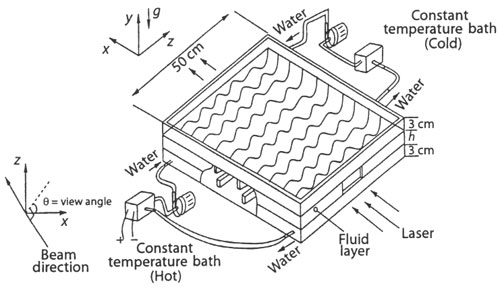
Figure 4.46: Schematic of the experimental appratus
|