To illustrate fringe formation in the infinite fringe setting, a candle flame was put in the path of the test beam and the Interferograms was recorded. The candle flame in the infinite fringe setting is shown in figure 4.11. The fringes can be seen to correspond to isotherms around the candle flame.
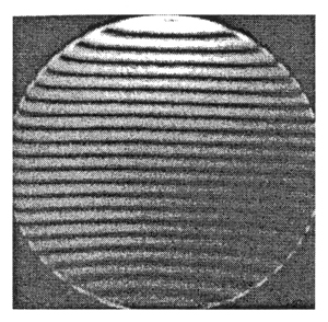
Figure 4.12: Wedge Fringe setting of the interferometer |
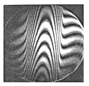
Figure 4.13: Candle Flame in the wedge fringe setting
|
The wedge fringe setting is comparatively easier to setup than the infinite fringe setting. Here the initial fringes from due to deliberate misalignment between the optical components. initially the fringes are adjusted so that they are perfectly straight. Figure 4 shows the initial wedge fringe setting of the interferometer. If a thermal disturbance is introduced in the path of the test beam, the fringes get displaced to an extent depending on the nature of the temperature profile. Hence the fringes in the wedge fringe setting of the interferometer are representative of the temperature profile in the fluid medium under study. The candle flame experiment is shown in the wedge fringe setting mode in figure 5. Here the fringes are the temperature profile inside the flame.
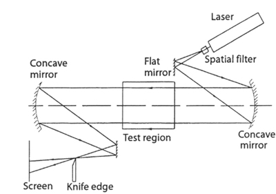
Figure 4.14 (a): Schematic drawing of a schlieren apparatus
For completeness, the schlieren and shadowgraph configurations are shown in figures 4.14 (a) and 4.14 (b), respectively. A combined Mach-Zehnder and Michel son interferometer for simultaneous measurement of thermal convection and crystal topography is shown in figure 4.15.
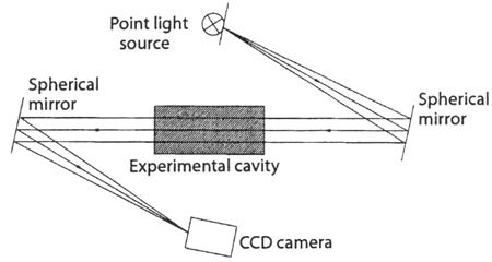
Figure 4.14 (b): Schematic drawing of a shadowgraph apparatus
|