| |
Penumatic Isolation Mount
The optical components of the interferometer are extremely sensitive to vibrations. This can be experienced from the movement of the fringes which form on the screen. To avoid ground vibration from reaching the optics, the entire interferometer is placed over four pneumatic isolation mounts. These mounts are connected to an air compressor for pressurization. Once the mounts are pressurized the entire interferometer floats over the mounts. This stabilizes the interferometric images and facilitates image acquisition. an air compressor of rated capacity 10atmospheres has been used throughout the experiment to pressurize the mounts. The operating pressure for the mounts is 5 kg/ A regulator valve was used to supply air to the mounts at the right pressure. The compressor in turn was located sufficiently far away from the interferometer to eliminate motor vibration. A regulator valve was used to supply air to the mounts at the right pressure. The compressor in turn was located sufficiently far away from the interferometer to eliminate motor vibration.
Alignment of the Interferometer
Before the start of the experiment the interferometer has to be aligned. Though the initial alignment of the interferometer is generally not disturbed from one experiment to the other, periodic fine tunning is essential to ensure that the interferometer is operating at its highest sensitivity. The initial alignment of the interferometer is carried out as per the following steps:
- The light output of the spatial filter is adjusted so that the diffraction rings, which appears with the expanded beam, vanish. This requires adjustment of the screws on the spatial filter. In most experiments, the diffraction ring formed a complete circle and remained outside the periphery of the expanded beam.
- The laser power output is measured using a light meter. The laser-power output is generally not a stable quantity and changes with time. This change in power output is generally not a stable quantity and changes with time. This change in power output is not a transient phenomena. Instead, it decreases steadily with the hours of operation. During the present work, the laser output was in the range 30-32 mW over two years.
- The convex lens is adjusted from the pinhole of the spatial filter so that the distance of separation is the focal length of the lens. This produces a parallel laser beam needed for the experiments.
- All the optical components of the interferometer are adjusted until their centers fall on a horizontal plane. Once this is accomplished, the first beam splitter is adjusted until it is at 45 degrees to the incoming light rays. All the remaining optical components are then made parallel to one another by turning one at a time. The mirrors and beam splitters being of 150 mm in diameter, the expanded beam of 70 mm diameter is made to pass through the central portion of the optical components.
- Adjustment for the infinite fringe setting is delicate and requires effort. In the infinite fringe setting, the initial field-of-view is one of the complete brightness since interference is constructive. The geometrical and the optical path lengths of the test and reference beams are then the same in the absence of any thermal disturbances in the path of the test beam. Owing to imperfect adjustment of the mirrors and beam splitters by screws moment, the exact infinite fringe setting, the distance between the fringes increases and the number of fringes decreases until the illuminated spot is spanned by one or two broad fringes. In the present work, it was possible to reduce the number of fringes to unity at the start of all the experiments. (Fig 4.10)
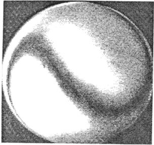
Figure 4.10: Infinite fringe setting of the interferometer
|
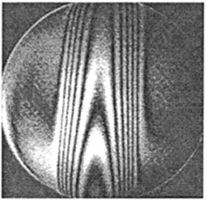
Figure 4.11: Candle Flame in the infinite fringe setting
|
more...
|