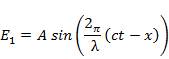
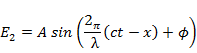
E is, in general, a vector but in measurements one works with light beams that are nearly
parallel. Hence it is sufficient to consider the magnitude of E but not its direction. Two
monochromatic wave fronts arising from a single light source and having a phase difference
are represented by the equations,
Interferometric measurements are based on information contained in above equation. The
phase difference  is equivalent to a path difference is equivalent to a path difference  where where

is called as the optical path length between a pair of points, in contrast to the geometric
path length represented by the  -coordinate. Geometric path length forms the basis
of distance measurement while the phase difference forms the basis of distance, speed,
density and temperature measurements. These measurements are, however, possible only
if the phase difference is stable and independent of time. This required the light source
to be coherent. The laser is a high quality monochromatic coherent light source and is
hence suitable for optical instrumentation. -coordinate. Geometric path length forms the basis
of distance measurement while the phase difference forms the basis of distance, speed,
density and temperature measurements. These measurements are, however, possible only
if the phase difference is stable and independent of time. This required the light source
to be coherent. The laser is a high quality monochromatic coherent light source and is
hence suitable for optical instrumentation.
Interference
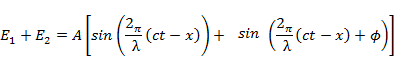
Consider the superposition of two nearly parallel waves that originate from the same
monochromatic light source; the waves have a phase difference . Their amplitudes are
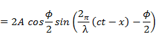
taken to be equal. Superposition results in the following development:
The intensity  of the combined beam is of the combined beam is  and is plotted in Figure 4.1.
To the human eye, intensities below a certain threshold would be seen as dark while
intensities above would be bright. Light sensors can, of course, detect small changes in
intensity. To an observer, the intensity distribution of Figure 4.1 is a sequence of dark
and bright patches, called fringes. With reference to Figure 4.1, the superposition of two
light beams with uniform intensity but a phase difference results in an interference pattern
consisting of alternately dark and bright regions, the fringes. The spacing between two
lines corresponding to the highest intensity is called as a fringe shift and is marked and is plotted in Figure 4.1.
To the human eye, intensities below a certain threshold would be seen as dark while
intensities above would be bright. Light sensors can, of course, detect small changes in
intensity. To an observer, the intensity distribution of Figure 4.1 is a sequence of dark
and bright patches, called fringes. With reference to Figure 4.1, the superposition of two
light beams with uniform intensity but a phase difference results in an interference pattern
consisting of alternately dark and bright regions, the fringes. The spacing between two
lines corresponding to the highest intensity is called as a fringe shift and is marked  in the figure. This fringe shift is also obtained as the spacing between adjacent lines of minimum intensity. in the figure. This fringe shift is also obtained as the spacing between adjacent lines of minimum intensity.
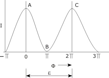
Figure 4.1: Intensity as a Function of Phase Difference between Interfering Light Beams.
|