In CNC machine tool, each axis of motion is equipped with a driving device to replace the handwheel of the conventional machine tool. A axis of motion is defined as an axis where relative motion between cutting tool and workpiece occurs. The primary axes of motion are referred to as the X, Y, and Z axes and form the machine tool XYZ coordinate system. Figure 7.1.3 shows the coordinate system and the axes of motion of a typical machine tool. Conventionally machine tools are designated by the number of axes of motion they can provide to control the tool position and orientation.
2.1 2-axis machine tool
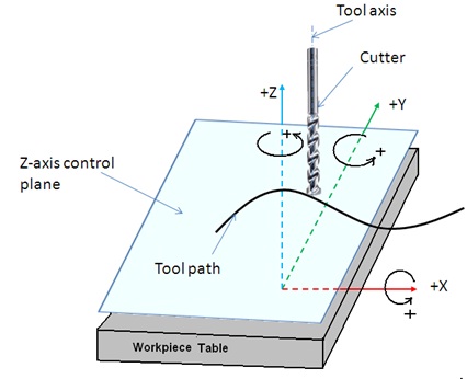
Figure 7.1.3 Axes of motion of a machine tool
If the machine tool can simultaneously control the tool along two axes, it is classified as a 2-axis machine. The tool will be parallel and independently controlled along third axis. It means that machine tool guided the cutting tool along a 2-D contour with only independent movement specified along the third axis. The Z-axis control plane is parallel to the XY plane.
2.2 2.5-axis machine tool
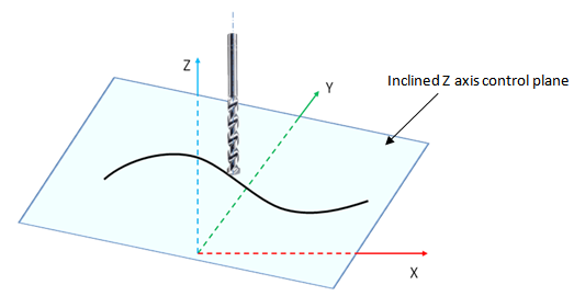
Figure 7.1.4 Axes in 2.5-axis machine tool
In this type of machine tool, the tool can be controlled to follow an inclined Z-axis control plane and it is termed as 2.5-axis machine tool. Figure 7.1.4 explains the axes system in 2.5-axis machine tool.
2.3 3-axis and multiple axis machine tool
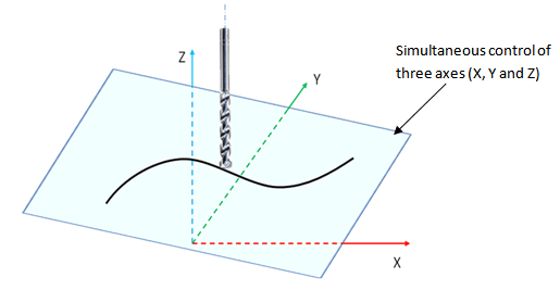
Figure 7.1.5 3-axis machine tool
In these CNC machine tools, the tool is controlled along the three axes (X, Y, and Z) simultaneously, but the tool orientation doesn’t change with the tool motion as shown in Figure 7.1.5.
If the tool axis orientation varies with the tool motion in 3D, 3-axis machine gets converted into multi-axis orientation machine (4-, 5-, or 6-axis). Figure 7.1.6 shows the schematic of tool motion in a multi-axis CNC machine tool.
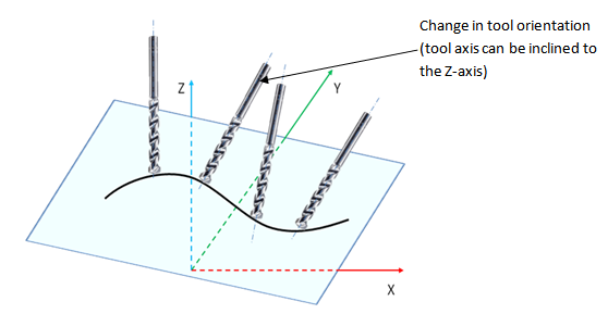
Figure 7.1.6 Multiple axes machine tool