2. Unloading Valve
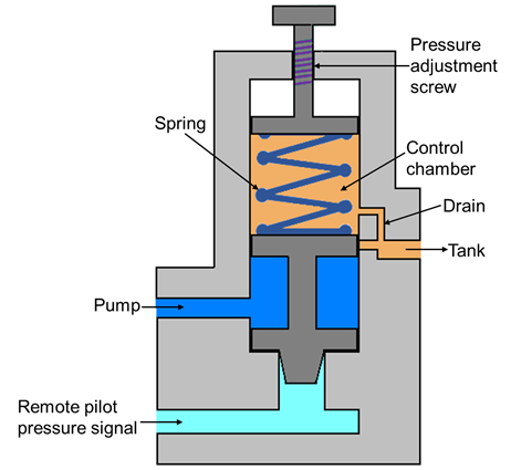
Figure 5.6.2 Unloading Valve
Construction of the unloading valve is shown in Figure 5.6.2. This valve consists of a control chamber with an adjustable spring which pushes the spool down. The valve has two ports: one is connected to the tank and another is connected to the pump. The valve is operated by movement of the spool. Normally, the valve is closed and the tank port is also closed. These valves are used to permit a pump to operate at the minimum load. It works on the same principle as direct control valve that the pump delivery is diverted to the tank when sufficient pilot pressure is applied to move the spool. The pilot pressure maintains a static pressure to hold the valve opened. The pilot pressure holds the valve until the pump delivery is needed in the system. As the pressure is needed in the hydraulic circuit; the pilot pressure is relaxed and the spool moves down due to the self-weight and the spring force. Now, the flow is diverted to the hydraulic circuit. The drain is provided to remove the leaked oil collected in the control chamber to prevent the valve failure. The u nloading valve reduces the heat buildup due to fluid discharge at a preset pressure value.